Multichannel ultrahigh radio frequency identification system

A radio frequency identification system, ultra-high frequency technology, applied in the field of ultra-high frequency RFID radio frequency identification system, can solve the problems of redundant lines, high product failure rate, high cable cost, etc., and achieve the effect of solving complex connection

Inactive Publication Date: 2015-02-04
XIAMEN XINDECO IOT TECH
View PDF4 Cites 2 Cited by
  • Summary
  • Abstract
  • Description
  • Claims
  • Application Information

AI Technical Summary

Problems solved by technology

[0003] Specifically, assuming that the multi-channel UHF RFID system is connected with 4 antennas, that is, when X=4, log 2 4≤N2 4 + 1, then N=2, so the total number of cables used to connect the RFID reader 1' and the RF switch control board 2' inside the RFID system is: 2 signal cables, 1 power cable, 1 RF coaxial cables, which will easi

Method used


Image

  • Multichannel ultrahigh radio frequency identification system
  • Multichannel ultrahigh radio frequency identification system
  • Multichannel ultrahigh radio frequency identification system

Examples


Embodiment Construction

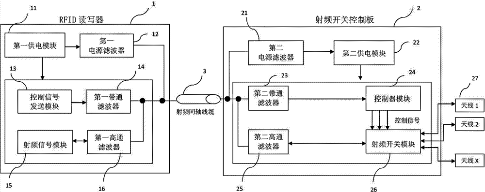
[0024] Such as figure 2 As shown, the present invention discloses a novel multi-channel ultra-high frequency RFID radio frequency identification system, which includes an RFID reader 1, a radio frequency switch control board 2 and a radio frequency coaxial for transmitting power, control and radio frequency signals cable3.

[0025] The RFID reader 1 includes a first power supply module 11 , a first power supply filter 12 , a control signal sending module 13 , a first band-pass filter 14 , a radio frequency signal module 15 and a first high-pass filter 16 .

[0026] The radio frequency switch control board 2 includes a second power filter 21 , a second power supply module 22 , a second bandpass filter 23 , a controller module 24 , a second high pass filter 25 , a radio frequency switch module 26 and several antenna units 27 .

[0027] The first power supply module 11 is preferably a DC power supply, which is divided into two power supply outputs, one of which supplies power t...


PUM


Abstract

The invention discloses a multichannel ultrahigh radio frequency identification system which comprises an RFID (radio frequency identification) reader-writer, a radio frequency switch control board and a radio frequency coaxial cable. A low-pass filter, a band-pass filter and a high-pass filter are respectively added at power ends, control ends and radio frequency signal ends of the RFID reader-writer and the radio frequency switch control board, so that power, control signals and radio frequency signals share the radio frequency coaxial cable for transmission and are not easily mutually interfered, and the system effectively solves the technical problem that an RFID reader-writer and a radio frequency switch control board are complicatedly wired and easily generate faults.

Description

technical field [0001] The invention relates to the field of wireless radio frequency, in particular to a multi-channel ultra-high frequency RFID radio frequency identification system. Background technique [0002] Such as figure 1 As shown, a traditional multi-channel UHF radio frequency identification system generally consists of an RFID reader 1' and a radio frequency switch control board 2'; the reader 1' includes a first power supply module 11', a control signal sending module 12 'and a radio frequency signal module 13'; the radio frequency switch control board 2' includes a second power supply module 21', a relay amplifier 24', a radio frequency switch module 22' and several antennas 23'. The first power supply module 11' is responsible for the power supply of the reader 1', and is electrically connected to the second power supply module 21' through a power cable 3'; the control signal sending module 12' is connected to the radio frequency switch module through N sign...

Claims


Application Information

Patent Timeline
IPC IPC(8): G06K17/00
Inventor 何昱旻王太平杨律青吕东海腾建财曾世超张河木
Owner XIAMEN XINDECO IOT TECH
Why Eureka
Try Eureka