
Ice melting power triangle based ice coating lead ice melting current obtaining method

A technology of power triangle and ice melting current, applied in the installation of electrical components, cables, overhead installation, etc., can solve the problems of calculation method error, poor engineering applicability, etc., to achieve small calculation error, strong engineering applicability, parameter Calculate simple effects

Active Publication Date: 2015-02-04
STATE GRID CORP OF CHINA +3
View PDF3 Cites 8 Cited by
  • Summary
  • Abstract
  • Description
  • Claims
  • Application Information

AI Technical Summary

Problems solved by technology

[0062] The purpose of the present invention is to solve the problem that the existing calculation methods of ice-melting power and ice-melting current have large errors, which lead to poor engineering applicability, and propose a method for obtaining ice-melting current of ice-coated conductors based on the ice-melting power triangle

Method used


Image

  • Ice melting power triangle based ice coating lead ice melting current obtaining method
  • Ice melting power triangle based ice coating lead ice melting current obtaining method
  • Ice melting power triangle based ice coating lead ice melting current obtaining method

Examples


specific Embodiment approach 1

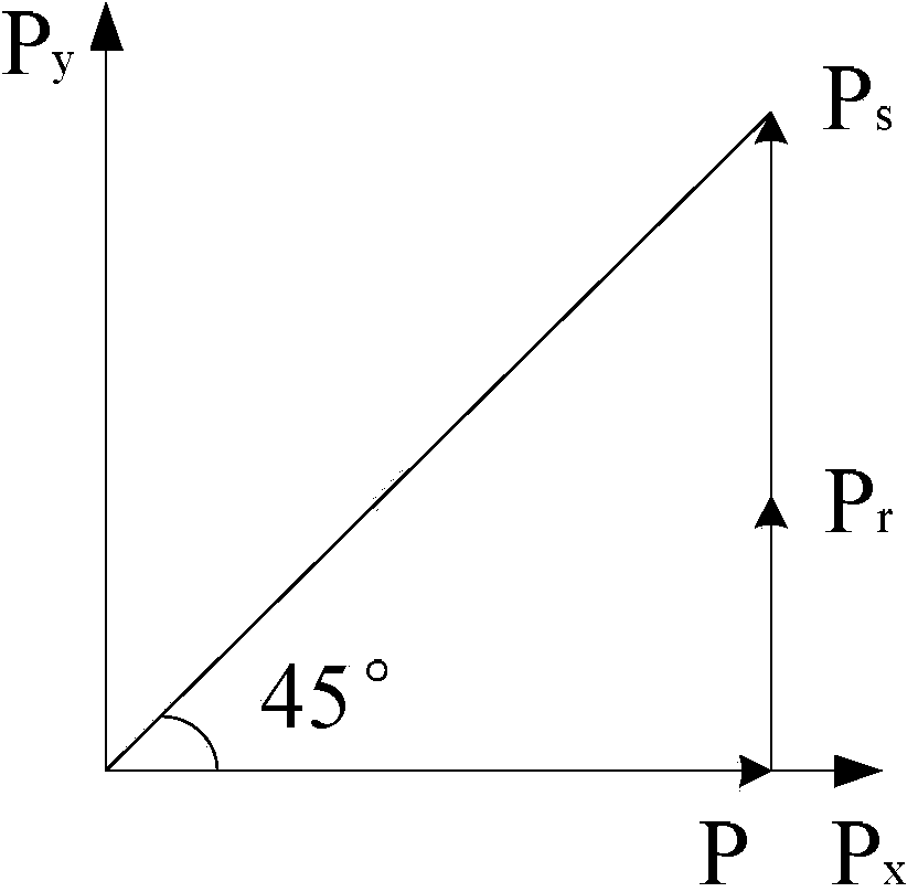
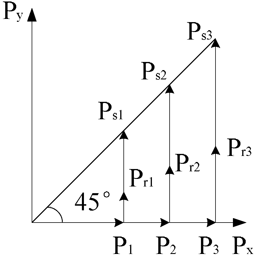
[0080] Specific implementation mode one: combine figure 1 and figure 2 To illustrate this embodiment, the method for obtaining the ice-melting current of an ice-coated conductor based on the ice-melting power triangle described in this embodiment includes the following steps:

[0081] Step 1. Establish ice-melting power triangle

[0082] In the plane Cartesian coordinate system P x OP y An isosceles right-angled triangle is established in the interior, and this isosceles right-angled triangle is the described ice-melting power triangle, and the three apex coordinates of this ice-melting power triangle are respectively (0, 0), (P, 0) and (P, P r +P s ), where P is the input power for melting ice, P r Absorbed power for icing, i.e. the total power needed to heat up and melt the icing body, P s for wire heating and ambient loss power, then

[0083] Step 2. Set P Q is the initial power, and 0Q x Take a point on the axis (P Q , 0), from the point (P Q ,0), (P,0) and (...

specific Embodiment approach 2

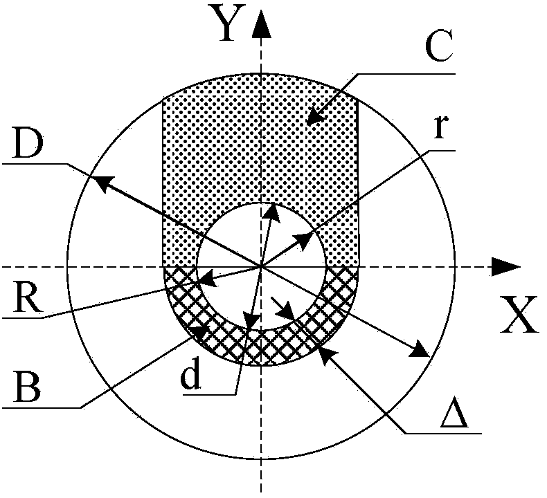
[0109] Specific implementation mode two: combination image 3 This embodiment is described. This embodiment is a further limitation of the method for obtaining the ice-melting current of the ice-coated conductor based on the ice-melting power triangle described in Embodiment 1. In this embodiment, the V s is calculated by the following formula:

[0110] V s =0.7854(D+d)(D-d) (25)

[0111] Among them, D is the diameter of the ice-covered body, and d is the diameter of the wire, such as image 3 shown.

specific Embodiment approach 3

[0112] Specific implementation mode three: combination image 3 This embodiment is described. This embodiment is a further limitation of the method for obtaining the ice-melting current of the ice-coated conductor based on the ice-melting power triangle described in Embodiment 1. In this embodiment, the V 3 is calculated by the following formula:

[0113] V 3 = B + C B = π ( r + Δ ) 2 - πr...


PUM


Abstract

The invention discloses an ice melting power triangle based ice coating lead ice melting current obtaining method and belongs to the technology of ice melting of an ice coating lead. The ice melting power triangle based ice coating lead ice melting current obtaining method aims at solving the problems that the engineering applicability is not strong due to the fact that the error of the existing calculation method of ice melting power and ice melting currents is large. The ice melting power triangle based ice coating lead ice melting current obtaining method comprises the following steps of firstly establishing an ice melting power triangle; enabling power P required for ice melting to be equivalent to a sum of an ice coating absorption power Pr and wasted power Ps of other parts; calculating the ice melting power under different set ice melting time; calculating ice melting ice currents. The ice melting power triangle based ice coating lead ice melting current obtaining method can describe a relationship between the ice melting power P and an ice coating parameter with high accuracy, is simple in parameter calculation, enables the calculation error to be smaller than 10%, is strong in engineering applicability and is applicable to ice melting and ice proof of the ice coating lead.

Description

technical field [0001] The invention relates to ice-melting technology for ice-coated conductors. Background technique [0002] Electric power accidents caused by grid icing have occurred frequently in my country and the world in recent years. At present, the most effective and commonly used ice melting method applied to the overhead power lines of the power grid is the Joule heating effect ice melting method. Including AC short circuit ice melting, DC short circuit ice melting, load adjustment ice melting, power grid current transfer ice melting, capacitor compensation inductance adjustment negative ice melting, parallel capacitor compensation ice melting, high frequency ice melting, etc. The basic principle of Joule heating effect ice melting is to use the Joule heating effect generated by the large current passing through the ice-coated power line to realize the function of heating the wire to melt the ice coating. The practical engineering application technologies are ...

Claims


Application Information

Patent Timeline
Patent Type & Authority Applications(China)
IPC IPC(8): H02G7/16
CPCH02G7/16
Inventor 刘刚梁岩陈永辉赵学增刘建军吴坚张竞伟刘勇军迟连道孙福军田伟王占伟都兴云
Owner STATE GRID CORP OF CHINA
Learn More