Pulse signal transformation circuit of initiating explosive device for satellite

A technology for converting circuits and pulse signals, applied in the field of satellite pyrotechnic pulse signal conversion circuits, can solve the problems of inability to accurately measure the current value of pulse signals, ground circuit interference, etc., and achieve the effects of simplifying circuit design, avoiding interference, and improving accuracy

Inactive Publication Date: 2015-02-04
HARBIN INST OF TECH
View PDF3 Cites 4 Cited by
  • Summary
  • Abstract
  • Description
  • Claims
  • Application Information

AI Technical Summary

Problems solved by technology

[0003] The purpose of the present invention is to solve the problem that the existing pyrotechnic pulse signal conversion circuit cannot accurately measure the pulse signal current value, and the ground circuit interferes with the satellite, and provides a satellite pyrotechnic product pulse signal conversion circuit

Method used


Image

  • Pulse signal transformation circuit of initiating explosive device for satellite
  • Pulse signal transformation circuit of initiating explosive device for satellite
  • Pulse signal transformation circuit of initiating explosive device for satellite

Examples


specific Embodiment approach 1

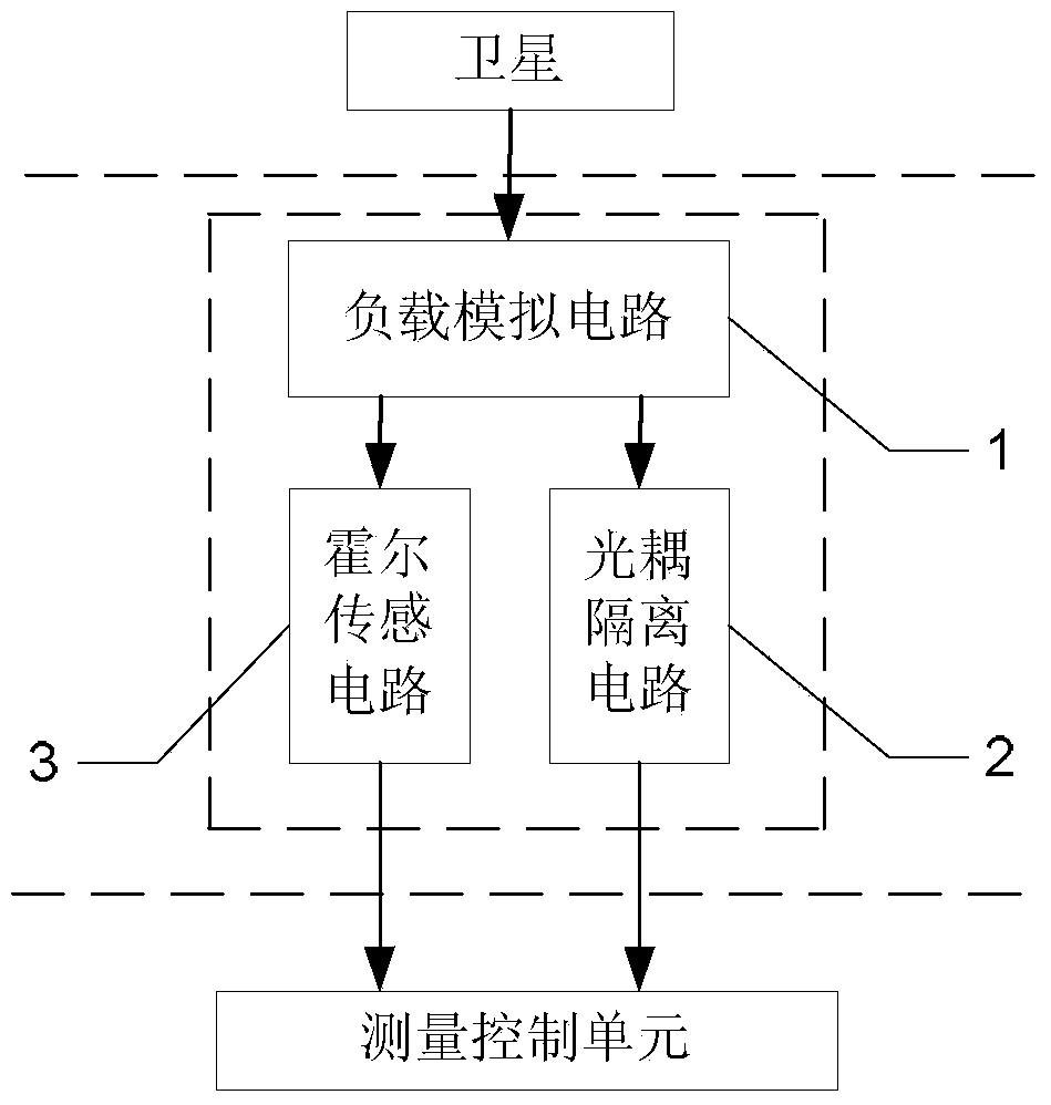
[0009] Specific implementation mode one: the following combination figure 1 and figure 2 Describe this embodiment, the satellite pyrotechnics pulse signal conversion circuit described in this embodiment, the conversion circuit includes a load simulation circuit 1, an optocoupler isolation circuit 2 and a Hall sensor circuit 3, and the load simulation circuit 1 simulates the pyrotechnics of the satellite. The product load, and then send the current signal to the optocoupler isolation circuit 2 and the Hall sensor circuit 3 at the same time, the optocoupler isolation circuit 2 converts the received current signal from analog to digital, and then sends it to the measurement control unit, the Hall sensor The sensing circuit 3 converts the received current signal into a voltage signal, and then sends the voltage signal to the measurement control unit;

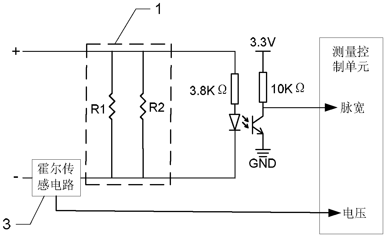
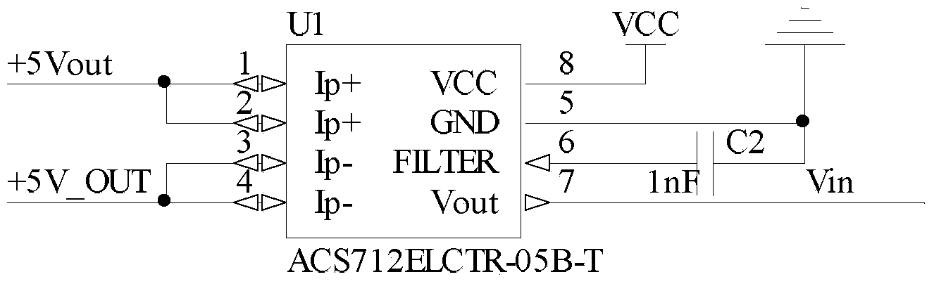
[0010] Load simulation circuit 1 includes two resistors R1 and R2 connected in parallel, optocoupler isolation circuit 2 uses Ag...

specific Embodiment approach 2

[0012] Embodiment 2: This embodiment further describes Embodiment 1. The R1 and R2 are: R1=R2=20Ω.

specific Embodiment approach 3

[0013] Embodiment 3: In this embodiment, Embodiment 1 is further described. The current-limiting resistance of the optocoupler isolation circuit 2 is 3.8KΩ.

[0014] In this embodiment, a 3.8KΩ current-limiting resistor is used to ensure that the current flowing through the optocoupler is about 10mA. When the current flowing through the optocoupler is 10mA, the optocoupler is turned on.


PUM


Abstract

The invention relates to a pulse signal transformation circuit of an initiating explosive device for a satellite, aiming at solving the problems that the existing pulse signal transformation circuit of the initiating explosive device for the satellite cannot accurately measure the current value of a pulse signal, and a ground circuit has interference to the satellite. The pulse signal transformation circuit of the initiating explosive device for the satellite comprises a load simulation circuit, an opto-coupling isolation circuit and a Hall sensing circuit, wherein the load simulation circuit simulates the loading of the initiating explosive device for the satellite and transmits a current signal to the opto-coupling isolation circuit and the Hall sensing circuit simultaneously, the opto-coupling isolation circuit converts the received current signal analog quantity to digital quantity and transmits the digital quantity to a measurement control unit, and the Hall sensing circuit converts the received current signal to a voltage signal and transmits the voltage signal to a measurement control unit; and the load simulation circuit comprises two resistors connected in parallel, the opto-coupling isolation circuit adopts an SCSL-6400 chip, and the Hall sensing circuit adopts an ACS712ELCTR-05B-T chip. The pulse signal transformation circuit is suitable for micro spacecrafts.

Description

technical field [0001] The invention relates to a pulse signal conversion circuit of a satellite pyrotechnic product. Background technique [0002] my country's high-tech aerospace field attaches great importance to the development of micro-spacecraft and key technologies. The safety design of small satellites mainly refers to the design of the pyrotechnic ignition control circuit and power supply interface design of the satellite. After the satellite is in orbit, if the solar panel cannot be deployed because it cannot be unlocked, the satellite will become a "waste star" due to lack of power. Therefore, the safety and reliability design of the small satellite is related to the success or failure of the satellite. The pulse signal of the pyrotechnic device is used as a direct trigger signal for the detonation of the pyrotechnic device. At the same time, the unlocking and separation control of many components on the star are completed by the detonation of the pyrotechnic devi...

Claims


Application Information

Patent Timeline
Patent Type & Authority Applications(China)
IPC IPC(8): H03K5/1252G01R19/25
Inventor 赵光权陆一波陈雪芹王峰朱秋扬闫冰清刘继红
Owner HARBIN INST OF TECH
Why Eureka
Try Eureka