Ultrasonically-actuated unit and ultrasonic processing device

A technology of working unit and processing device, applied in medical science, fluid using vibration, surgery, etc., can solve the problem of reduced processing performance at the top processing part

Active Publication Date: 2015-02-04
OLYMPUS CORP
View PDF7 Cites 4 Cited by
  • Summary
  • Abstract
  • Description
  • Claims
  • Application Information

AI Technical Summary

Problems solved by technology

As a result, the processing performance at

Method used


Image

  • Ultrasonically-actuated unit and ultrasonic processing device
  • Ultrasonically-actuated unit and ultrasonic processing device
  • Ultrasonically-actuated unit and ultrasonic processing device

Examples


no. 1 Embodiment approach

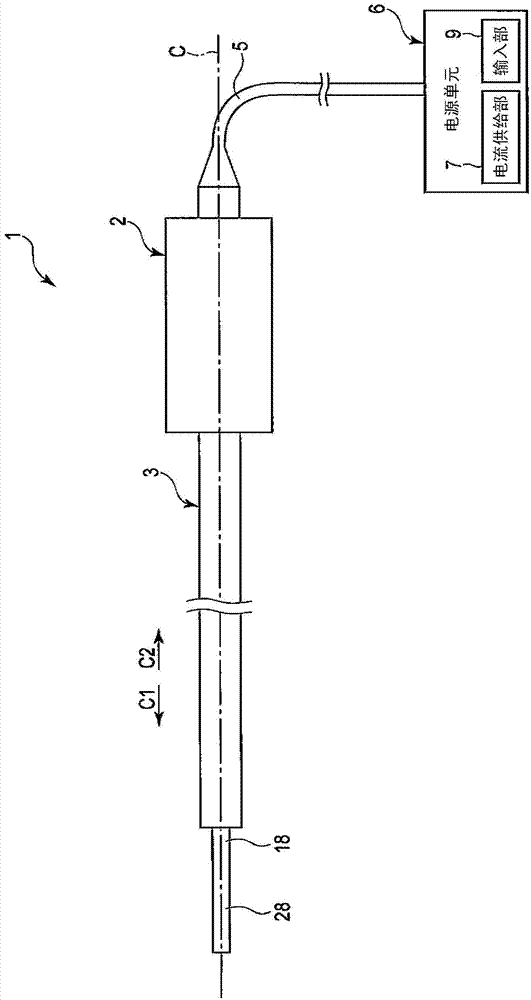
[0028] Reference Figure 1 to Figure 5 The first embodiment of the present invention will be described. figure 1 It is a figure which shows the ultrasonic processing apparatus 1 of this embodiment. Such as figure 1 As shown, the ultrasonic treatment device 1 has a longitudinal axis C. Here, one of two directions parallel to the longitudinal axis C is referred to as the tip direction ( figure 1 The direction of the arrow C1), and set the direction opposite to the tip direction as the proximal direction ( figure 1 The direction of the arrow C2). The ultrasonic processing apparatus 1 includes a vibrator housing 2 and a sheath 3 attached to the distal direction side of the vibrator housing 2. The sheath 3 extends along the length axis C. One end of the cable 5 is connected to the base end of the vibrator housing 2. The other end of the cable 5 is connected to the power supply unit 6. The power supply unit 6 includes a current supply unit 7 and an input unit 9.

[0029] figure 2 ...

no. 2 Embodiment approach

[0056] Next, refer to Figure 8 The second embodiment of the present invention will be described. The second embodiment is formed by modifying the structure of the first embodiment as follows. In addition, the same reference numerals are given to the same parts as in the first embodiment, and the description thereof is omitted.

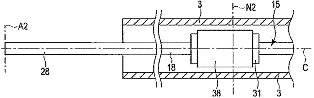
[0057] Figure 8 It is a figure which shows the internal structure of the sheath 3 of this embodiment. Such as Figure 8 As shown, in this embodiment, similar to the first embodiment, the node position N2 of the longitudinal vibration of the relay unit 32 at the reference frequency f0 is connected to the probe 18 of the ultrasonic wave transmission unit 15. Furthermore, a vibration absorbing part 38 is attached to the non-contact vibration part 31. That is, the non-contact vibration part 31 and the vibration absorption part 38 are located between the probe 18 and the sheath 3 as a distal-side transmission member in the radial direction.

[0058] However...


PUM


Abstract

This ultrasonically-actuated unit is provided with: an ultrasonic wave transmission unit that is provided along the lengthwise axis and transmits ultrasonic vibrations; a relay unit that, at a node position of longitudinal vibrations, is contiguous with the ultrasonic wave transmission unit or is connected to the ultrasonic wave transmission unit; and a non-contact vibration unit that can transmit improper vibrations, is provided along a direction parallel to the lengthwise axis in the state of not contacting the ultrasonic wave transmission unit, and to which improper vibrations are transmitted from the ultrasonic wave transmission unit via the relay unit. The ultrasonically-actuated unit is provided with a vibration absorbing unit that absorbs the improper vibrations transmitted to the non-contact vibration section.

Description

Technical field [0001] The present invention relates to an ultrasonic working unit that includes an ultrasonic transmission part extending along a longitudinal axis and capable of transmitting ultrasonic vibration from a proximal direction to a distal direction, and operates by being transmitted ultrasonic vibration. In addition, it relates to an ultrasonic treatment device provided with the ultrasonic working unit. Background technique [0002] Patent Document 1 discloses an ultrasonic working unit that operates by being transmitted ultrasonic vibration. This ultrasonic working unit includes an ultrasonic transmission part capable of transmitting ultrasonic vibration from the proximal direction to the distal direction. The ultrasonic transmission part includes: a horn member as a proximal-side transmission member to which an ultrasonic vibrator as an ultrasonic generation part is attached; and a probe as a distal-side transmission member connected to the distal direction side o...

Claims


Application Information

Patent Timeline
IPC IPC(8): A61B18/00
CPCA61B2017/320088A61B17/320068A61B2017/320072A61B2090/0817A61B2017/320073A61B2017/320089B06B1/0644
Inventor 铜庸高
Owner OLYMPUS CORP
Why Eureka
Try Eureka