Machine tool and machining method

A technology of processing method and working method, which is applied in the direction of metal processing, metal processing equipment, metal processing machinery parts, etc., can solve the problems of complicated structure of conveying line and difficulty in increasing conveying speed, so as to realize conveying efficiency, increase conveying speed, Realize the effect of cost

Active Publication Date: 2015-02-04
HONDA MOTOR CO LTD
View PDF6 Cites 13 Cited by
  • Summary
  • Abstract
  • Description
  • Claims
  • Application Information

AI Technical Summary

Problems solved by technology

As a result, the structure of the conveying line is complicated, and it is difficult to increase the conveying speed

Method used


Image

  • Machine tool and machining method
  • Machine tool and machining method
  • Machine tool and machining method

Examples


Embodiment

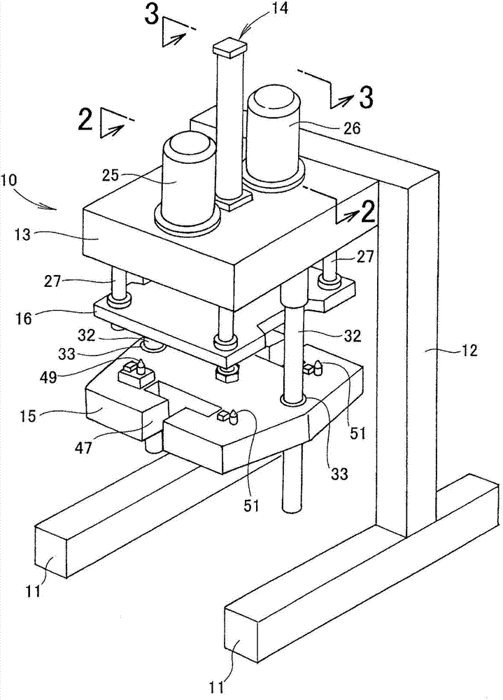
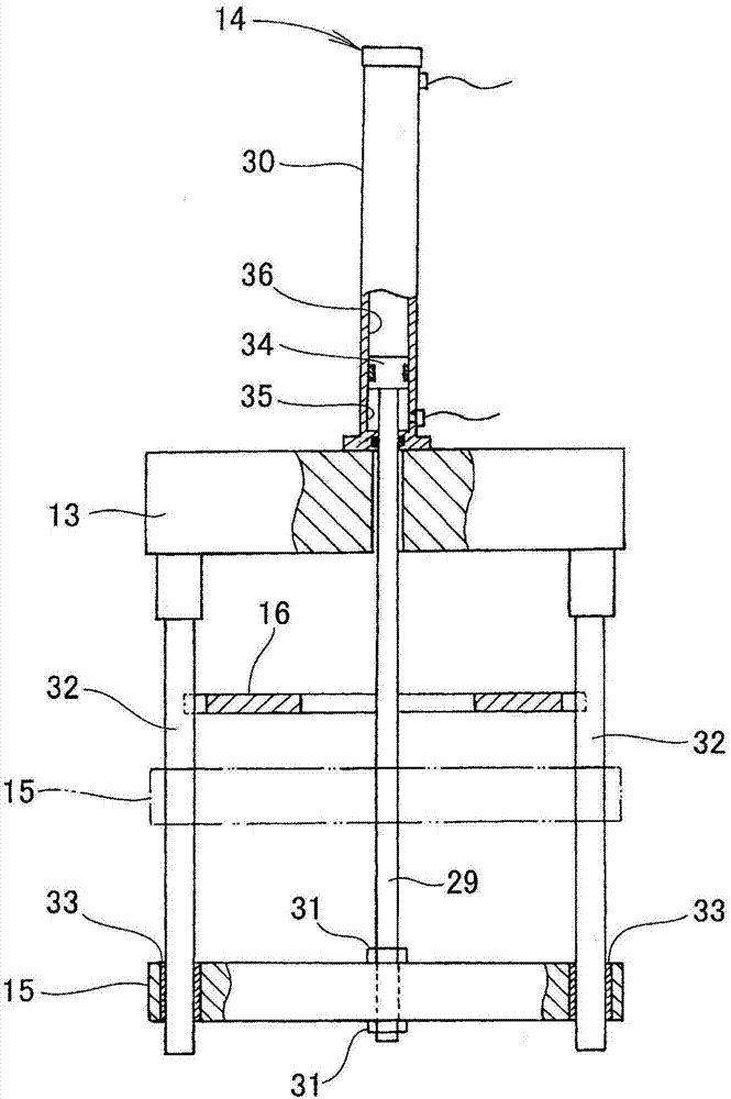
[0042] Such as figure 1 As shown, the machine tool 10 has: base frames 11, 11, which extend horizontally in a manner placed on a base or a chassis; an inverted U-shaped frame 12, which extends upward from these base frames 11, 11; a processing head 13, It is supported by the frame 12; a workpiece supporting plate moving mechanism 14, which is provided on the processing head 13; a workpiece supporting plate 15, which is moved up and down by the workpiece supporting plate moving mechanism 14; and a workpiece pressing plate 16, which is arranged on the processing head 13. Between the workpiece support plate 15 and the processing head 13.

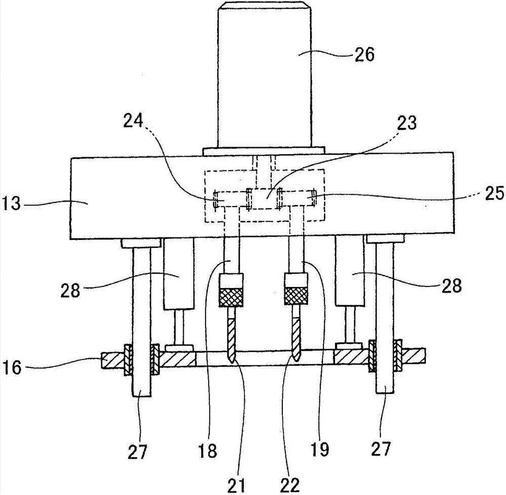
[0043] Such as figure 2As shown, the machining head 13 has a plurality (in this example two) of spindles 18, 19 extending downwardly. Cutting tools 21 , 22 such as drills and end mills are detachably attached to these spindles 18 , 19 .

[0044] A driving gear 23 and driven gears 24, 25 are built into the machining head 13, and the driving ...


PUM


Abstract

Disclosed is a machine tool for machining a workpiece (W1), which is held between a work-seating plate (15) and a work-pressing plate (16), using a cutters (21, 22) in a machining head (13). When machining has ended, the work-seating plate (15) is lowered and a machined workpiece (W2) is transferred to a support bar (43). Receiving pins (44, 45) are fitted into engaging holes (66, 67), respectively, of the workpiece (W2). The machined workpiece (W2) is carried in this manner from the work-seating plate (15) to a conveyance jig (50).

Description

technical field [0001] The present invention relates to a machine tool, in particular to an improved machine tool which transports a workpiece by a workpiece conveying mechanism and processes the workpiece by a processing head. Background technique [0002] For example, as disclosed in Patent Document 1, there is known a machine tool that performs machining on a workpiece using a machining head called a combination head. [0003] As disclosed in Patent Document 1, the machining unit includes six multi-axis machining heads, and moves in the horizontal direction so as to contact or separate from the clamp unit. The clamping unit is arranged on the conveying line. The clamping unit is transported along the transport line in a horizontal direction orthogonal to the horizontal direction. The clamping unit has advancing and retracting arms, and the workpiece is clamped by these advancing and retracting arms. [0004] In the structure of the processing apparatus disclosed in Pat...

Claims


Application Information

Patent Timeline
Patent Type & Authority Applications(China)
IPC IPC(8): B23Q3/06B23B39/16B23B47/28B23Q7/14
CPCB23B39/16B23Q3/18B23Q7/14
Inventor 荒川修吾山浦祐纪松永直也
Owner HONDA MOTOR CO LTD
Why Eureka
Try Eureka