Structure of a stapling device

A nailing machine and nailing technology, applied in nailing tools, U-shaped nailing tools, manufacturing tools, etc., to achieve the effects of prolonging service life, reducing slack, and high safety

Inactive Publication Date: 2015-02-11
JANN YEI IND
View PDF6 Cites 4 Cited by
  • Summary
  • Abstract
  • Description
  • Claims
  • Application Information

AI Technical Summary

Problems solved by technology

[0005] In view of this, the inventor aimed at the many defects and inconveniences caused by the imperfect structural design of the above-mentioned metal shell nailing machine, and deeply conceived, and actively researched and improved the trial production to develop and design this case

Method used


Image

  • Structure of a stapling device
  • Structure of a stapling device
  • Structure of a stapling device

Examples


Embodiment Construction

[0045] In order to further explain the technical solution of the present invention, the present invention will be described in detail below through specific examples.

[0046] The present invention is a nailing machine structure, and the accompanying drawings illustrate specific embodiments of the present invention and its components, all references to front and rear, left and right, top and bottom, upper and lower, and horizontal and vertical are only It is used for convenience of description, and does not limit the invention, nor restrict its components to any position or orientation in space. The dimensions specified in the drawings and description can be changed according to the design and requirements of the specific embodiments of the present invention without departing from the patent scope of the present invention.

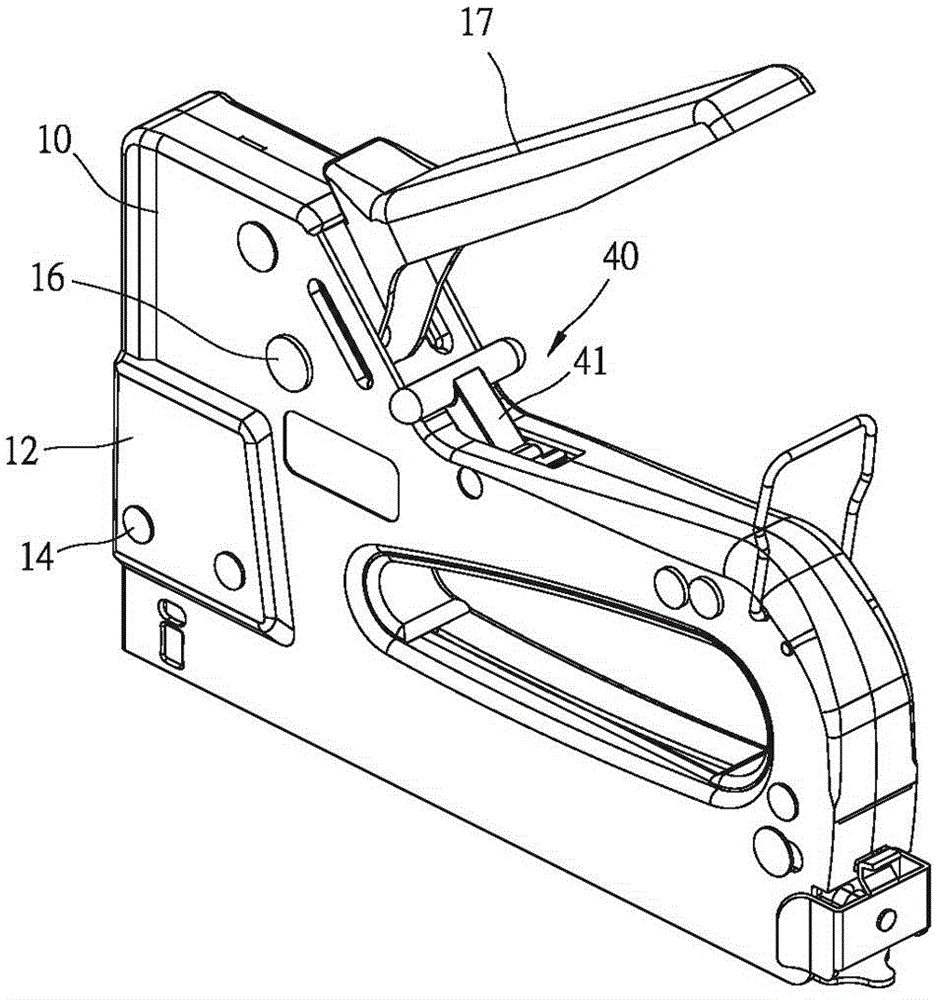
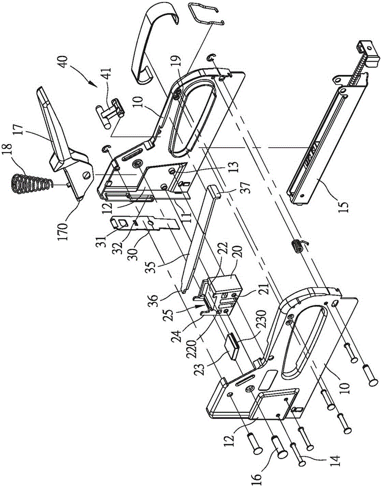
[0047] For the brief composition of the structure of the nailing machine of the present invention, please refer to figure 1 , figure 2 As shown, it has...


PUM


Abstract

A stapling device includes two casing members, a pad seat, and a striker plate. The casing members, which can be combined together, have front ends respectively forming front-end plates abutting each other. The two casing members are rotatably coupled to a press-down handle that is selectively pressed down. The pad seat is set at the front end of the interior of the two combined casing members. The pad seat has a front end face, which define, collectively with the inside surfaces of the front-end plates of the two casing members, a striker plate channel. The striker plate is slidably received in the striker plate channel. The striker plate is selectively pulled by the press-down handle to move upward. The two casing members clamp and retain therebetween a spring plate for providing a striking pre-loading force to the striker plate.

Description

technical field [0001] The invention relates to a metal shell nailing machine, in particular to a structure of the metal shell nailing machine which can simplify the structure, so as to reduce the assembly cost by reducing components, and has a buffer function to prolong the service life of the nailing machine. Background technique [0002] In woodworking, decoration, leather and other operations, it is often necessary to use nails to combine objects. In order to improve the working efficiency and nailing effect, the industry has developed a nailing machine that can continuously nail. It is mainly formed on the bottom of the casing. The nail groove group is used for accommodating nail needles and is automatically fed. In addition, there is a nail driving piece on the front edge of the casing that can be strongly fired downward by the action of the elastic member. When the nail driving piece is selectively lifted up by the pressure handle, the bottom The nails in the nail gro...

Claims


Application Information

Patent Timeline
Patent Type & Authority Applications(China)
IPC IPC(8): B25C1/02
CPCB25C5/06B25C5/11
Inventor 陈东益
Owner JANN YEI IND
Why Eureka
Try Eureka