
Eureka
For R&D, Eureka makes reading and utilizing patents & technical documents easy.
Eureka AIR
Designed for self-driven R&D workflows. Generate viable solutions, solve complex R&D challenges, empower your innovation with AI.

Eureka Materials
Designed for material experts only. Revolutionize your material R&D, from search, analyze, to developing new materials.

TechResearch
Generate reliable direction feasibility study reports for your R&D in just a few steps.

TechSeek
Discover and master advanced knowledge NOW. Basics, ideas, possibilities, all at once.

TechMind
As an expert in R&D Theories, TechMind can generates customized viable solutions instantly.

TechRisk
Analyze your overall solution with one click, know your potential R&D risks in advance.

TechMonitor
Get weekly tech updates, stay abreast of the latest tech innovations and key insights.
Spinning machine and a false twisting device
A textile machine, false twisting technology, applied in the direction of textiles and papermaking, spinning machine, continuous winding spinning machine, etc., can solve problems such as inability to adjust belt tolerance or wear
- Summary
- Abstract
- Description
- Claims
- Application Information
AI Technical Summary
Problems solved by technology
Method used
Image

Examples
Embodiment Construction
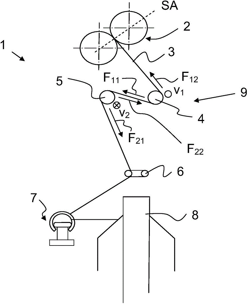
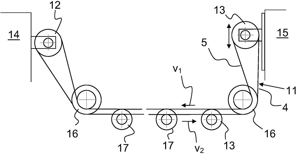
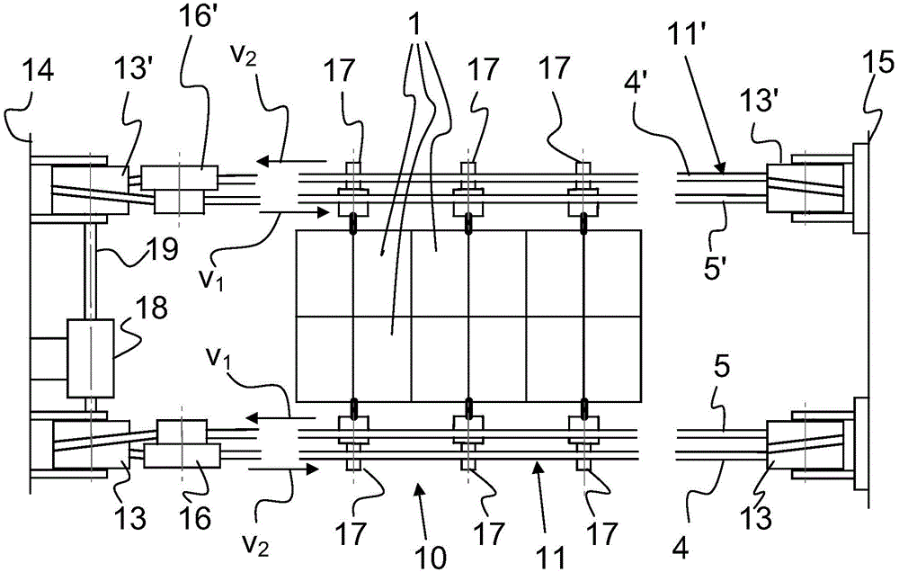
[0042] exist figure 1 The weaving unit 1 of the weaving machine 10 is schematically and partially shown in FIG. The delivery roll pair 2 of the drafting unit, not shown, supplies the ply strand 3 and forms the drafting unit output SA. The strand 3 turns around a first plastic belt 4 and then around a second plastic belt 5 . Subsequently, the ply thread passes through the twist stopper 6 and the traveler 7 and is wound on the bobbin 8 . The first plastic belt 4 and the second plastic belt 5 form a false twist device 9 . The two plastic belts 4 and 5 can refer to two separate belts 4 and 5 or to stretching and pushing return sections of a single belt.
[0043] The first plastic belt 4 and the second plastic belt 5 or the two runs have opposite directions of movement. Since the yarn lies flat on two belts moving in opposite directions, the yarn is stretched in one direction by one return and in the other direction by the other return. The yarn is deflected in the direction ...
PUM
 Abstract
Description
Claims
Application Information
 - R&D Engineer
- R&D Manager
- IP Professional
- Industry Leading Data Capabilities
- Powerful AI technology
- Patent DNA Extraction
Browse by: Latest US Patents, China's latest patents, Technical Efficacy Thesaurus, Application Domain, Technology Topic, Popular Technical Reports.
© 2024 PatSnap. All rights reserved.Legal|Privacy policy|Modern Slavery Act Transparency Statement|Sitemap|About US| Contact US: help@patsnap.com