Fluid Injector And Method For Operating Fluid Injector

A fluid injector and fluid injection technology, which is applied in the direction of fuel injection devices, fuel injection control, special fuel injection devices, etc., can solve problems such as the reduction of electrical signal amplitude, and achieve the effect of quality improvement

Active Publication Date: 2015-02-11
VTESCO TECH GMBH
View PDF7 Cites 4 Cited by
  • Summary
  • Abstract
  • Description
  • Claims
  • Application Information

AI Technical Summary

Problems solved by technology

As a disadvantage, this has the effect that the electrical signal amplitude will be reduced

Method used


Image

  • Fluid Injector And Method For Operating Fluid Injector
  • Fluid Injector And Method For Operating Fluid Injector
  • Fluid Injector And Method For Operating Fluid Injector

Examples


Embodiment Construction

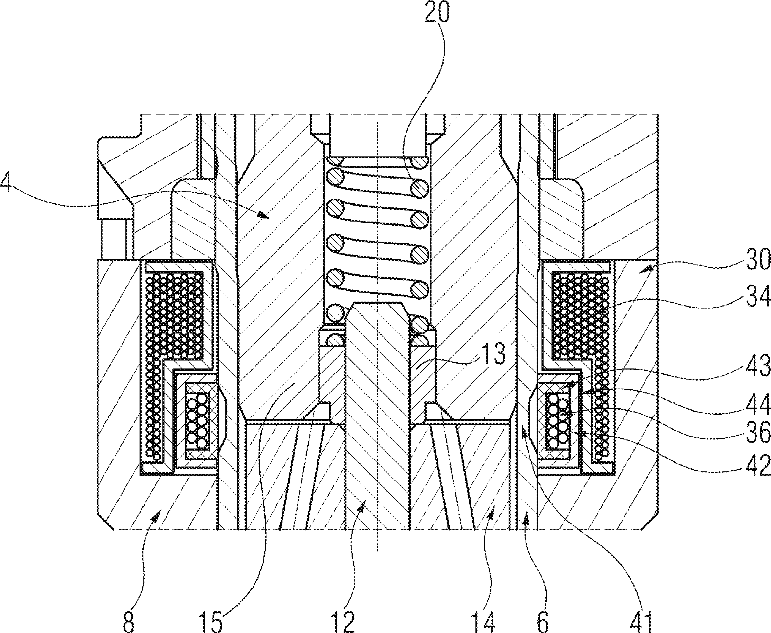
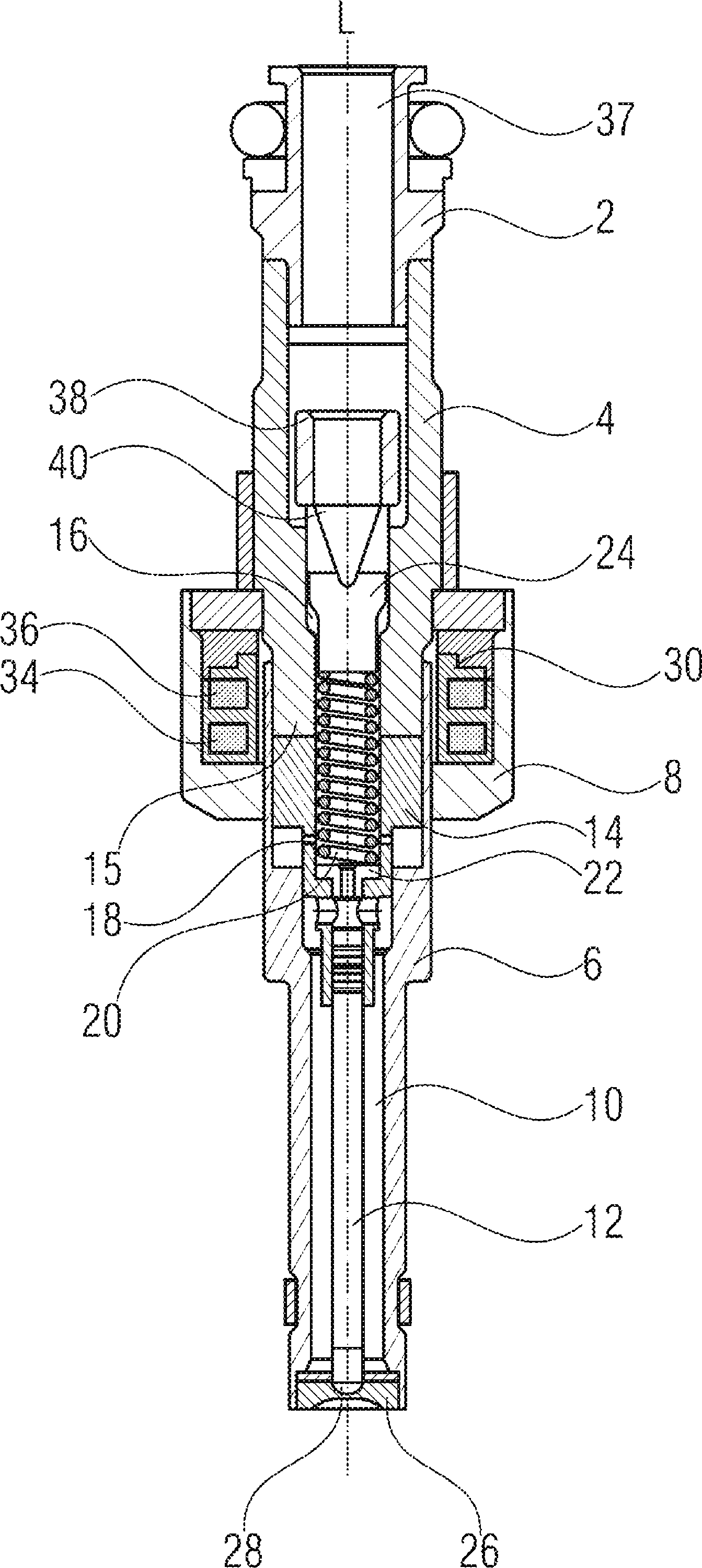
[0032] figure 1 A cross-sectional view of a known fluid injector is shown. The fluid injector is particularly suitable for dosing fluid, in particular fuel, into internal combustion engines. It comprises a fitting fitting 2 designed to mechanically and hydraulically couple the fluid injector to a fluid reservoir such as a fuel rail. The fluid injector has a longitudinal axis L and further comprises an inlet tube 4 , a valve body 6 and a housing 8 . Provided in the valve body 6 is a recess 10 which receives the valve needle 12 and preferably the armature 14 .

[0033] Valve needle 12 is mechanically coupled to armature 14 . in accordance with figure 1 In the case of a valve needle, the armature 14 is rigidly coupled to the valve needle 12 such that they are fixed in position relative to each other.

[0034] The inlet pipe 4 is provided with a recess 16 which hydraulically communicates with the recess 10 of the valve body 10 through a central opening 18 of the armature 14 ....


PUM


Abstract

A fluid injector is specified. The fluid injector has a longitudinal axis (L) and comprises a valve body (6), a valve needle (12), being received in the valve body (6), being axially moveable and being operable to prevent a fluid injection in a closing position and to permit the fluid injection in further positions, an armature (14) being mechanically coupled to the valve needle (12) so that it is operable to displace the valve needle (12) away from the closing position, and a solenoid assembly (30) comprising at least a first and second coil (34, 36) and being operable to magnetically actuate the armature (14) via an electrical signal (I 1 ). A method for operating the fluid injector comprises applying the electrical signal (I 1 ) to the first coil (34) to generate a primary magnetic field to move the armature (14) for displacing the valve needle (12) away from the closing position, evaluating a voltage (U 1 ) across terminals of the first coil (34), and controlling the second coil (36) with a further electrical signal (I 2 ) to saturate a magnetic field in a portion of the valve body (6) which is located between the armature (14) and the solenoid assembly (30) during evaluating the voltage (U 1 ).

Description

technical field [0001] The present disclosure relates to a fluid injector comprising: a longitudinal axis; a valve needle axially movable and operable to prevent fluid injection in a closed position and to permit fluid injection in other positions; an armature mechanically coupled to the valve needle; and a solenoid assembly comprising at least first and second coils and operable to magnetically actuate the armature via an electrical signal. The disclosure further relates to methods for operating the fluid injector. Background technique [0002] Fluid injectors are widely used, particularly for internal combustion engines, where they may be configured to dose fluid into the intake manifold of the internal combustion engine or directly into the combustion chambers of the cylinders of the internal combustion engine. [0003] The corresponding fluid injectors may be adapted to dose fluids at very high pressures in order to enhance the combustion process in view of the generati...

Claims


Application Information

Patent Timeline
Patent Type & Authority Applications(China)
IPC IPC(8): F02M51/06F02D41/20
CPCF02D2041/2055F02M51/0617F02D2041/2079F02M51/0621F02D2200/063F02D2041/2051F02D41/247F02D41/20F02M65/005F02M2200/08F02M2200/9053
Inventor S.菲利皮M.格兰迪F.伦齐V.波利多里
Owner VTESCO TECH GMBH
Why Eureka
Try Eureka