
Mounting member for vibration damping device and vibration damping device using the same

By combining resin fastening members and metal cylindrical fitting members, the problems of complex structure and insufficient vibration isolation performance of existing vibration isolation devices are solved, and a vibration isolation device with a lightweight, compact structure and excellent vibration isolation performance is realized.

Active Publication Date: 2015-02-11
SUMITOMO RIKO CO LTD
View PDF9 Cites 5 Cited by
  • Summary
  • Abstract
  • Description
  • Claims
  • Application Information

AI Technical Summary

Problems solved by technology

[0006] However, since the structure disclosed in U.S. Patent No. 5,964,456 requires fixing bolts to fix the first mounting member to the support, the number of parts increases, causing a problem of complicated structure, and at the same time, the structure needs to use a large fixing bolt. Bolts are used to securely fix the first mounting member to the stand, which tends to cause problems with increased weight
In addition, installing the fixing bolt requires a multi-turn operation, which is cumbersome and time-consuming, and at the same time causes another problem: it is difficult to control the fixing force by the tightening torque of the fixing bolt
However, according to this structure of Japanese Patent Laid-Open No. 2013-108522, bolts for fixing the first mounting member to the stand are no longer required, which inevitably leads to an increase in the size of the joint between the first mounting member and the stand. The problem
Also, by arranging the large plate to bend and wrap around the outside of the stand, there is a potential problem of upsizing the first mounting member itself
[0009] Therefore, it is difficult to say that the structure described in Japanese Patent Laid-Open No. 2010-048281 and / or 2013-108522 is good for the first mounting member, which means that there is room for improvement

Method used


Image

  • Mounting member for vibration damping device and vibration damping device using the same
  • Mounting member for vibration damping device and vibration damping device using the same
  • Mounting member for vibration damping device and vibration damping device using the same

Examples


Embodiment Construction

[0070] Embodiments of the present invention will be described below with reference to the drawings.

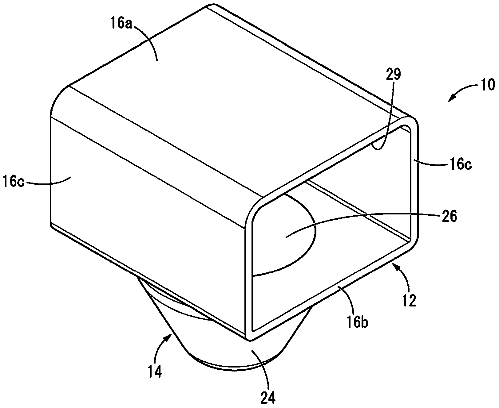
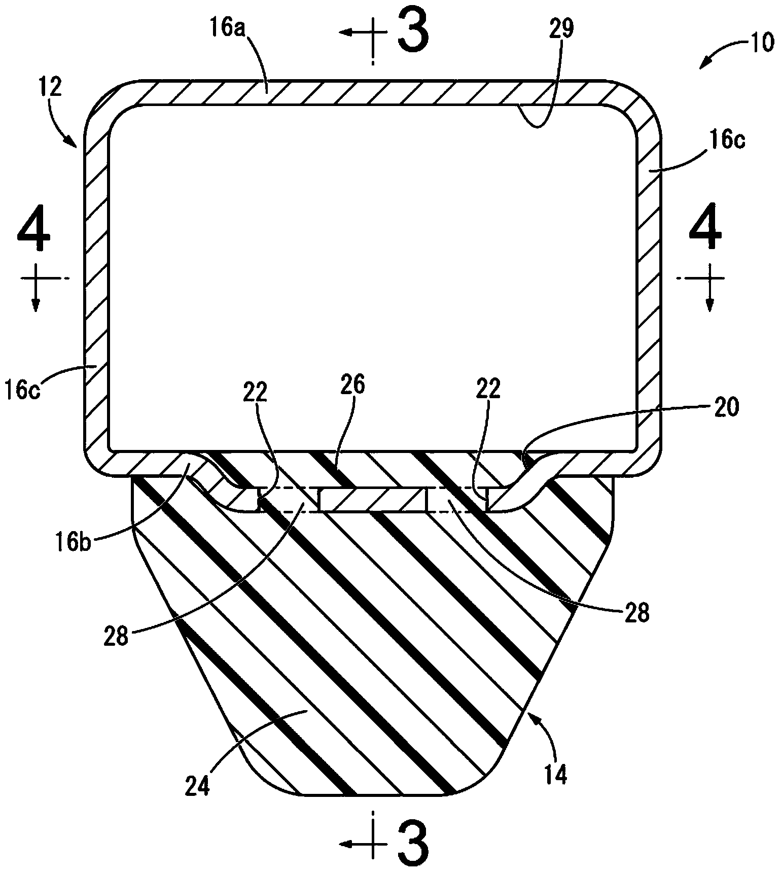
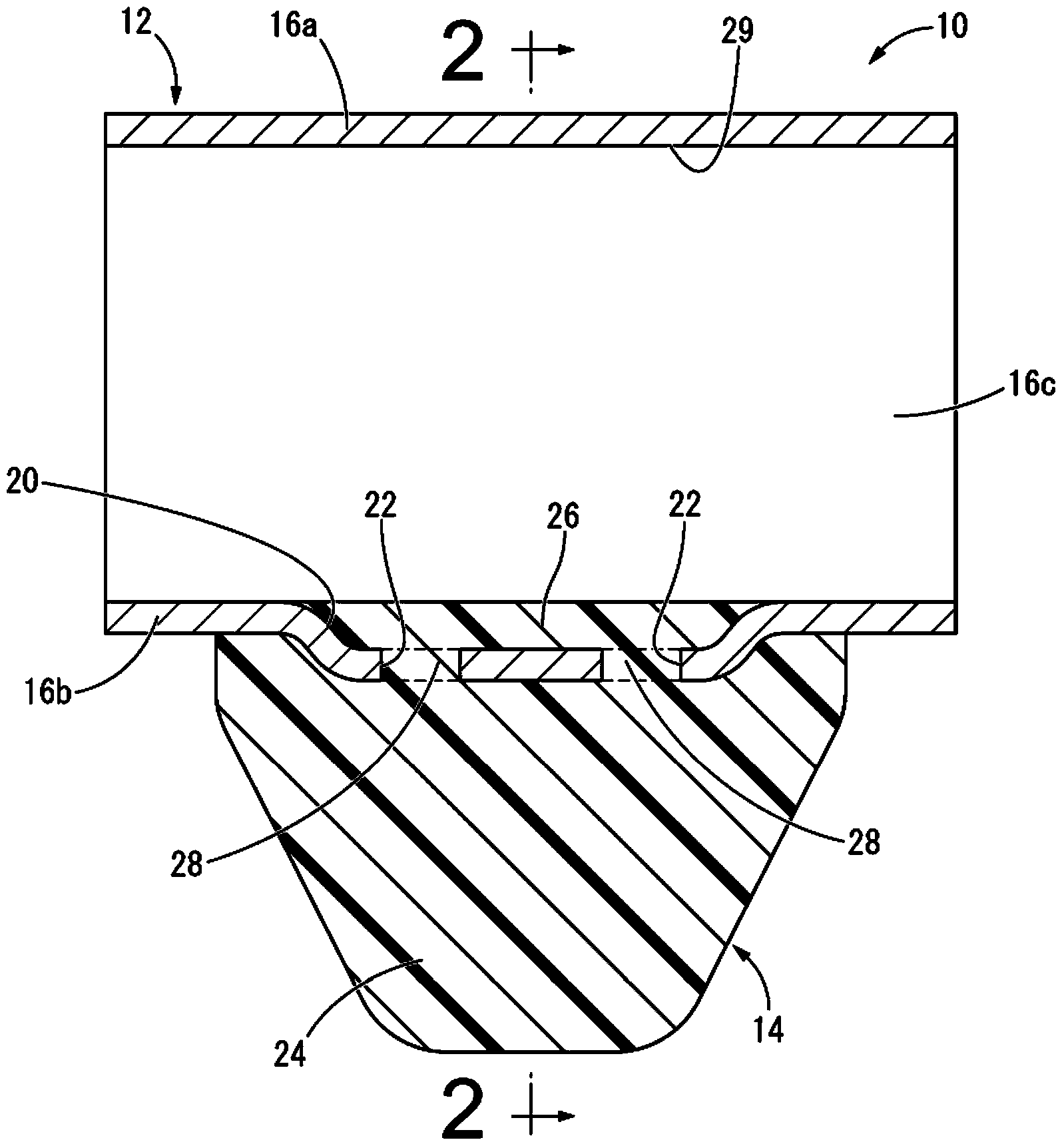
[0071] Figure 1 to Figure 4 A first mounting member 10 for a vibration isolator is shown as a first embodiment of the mounting member having structures according to the first to seventh aspects of the present invention. The first mounting member 10 is provided with a fastening member 14 and a cylindrical fitting member 12 made of metal serving as a fixing member. The up and down directions in the following descriptions usually refer to figure 2 in the up and down direction.

[0072] More specifically, the cylindrical fitting member 12 has a substantially quadrangular cylindrical shape having a peripheral wall portion formed by connecting the upper wall portion 16a and the lower wall portion 16b by a pair of side wall portions 16c, 16c, and the cylindrical shape The fitting member 12 is provided along the length direction ( image 3The center hole that passes through in t...


PUM


Abstract

A mounting member for use in a vibration damping device equipped with a main rubber elastic body and a bracket, including: a fixing member configured to be fixed to the bracket; an anchoring member made of resin and configured to be anchored to the main rubber elastic body. The anchoring member is anchored to the fixing member and protrudes from the fixing member.

Description

[0001] incorporation by reference [0002] The entire disclosures of Japanese Patent Application No. 2013-166143 filed on August 9, 2013 and Japanese Patent Application No. 2013-215226 filed on October 16, 2013 are incorporated herein by reference. technical field [0003] The present invention relates to a vibration isolating device to be used as an engine mount, a body mount, a sub-frame mount, etc. of a motor vehicle, and a mounting member for the vibration isolating device constituting the vibration isolating device. Background technique [0004] Conventionally, a vibration isolating device such as that disclosed in US Pat. No. 5,964,456 is known as one of a vibration isolating coupling or a vibration isolating support interposed between members constituting a vibration transmission system. The vibration isolation device has a structure in which a first mounting member and a second mounting member are elastically connected by a main rubber elastic body. [0005] Further...

Claims


Application Information

Patent Timeline
Patent Type & Authority Applications(China)
IPC IPC(8): F16F15/08F16F7/00F16F13/08B60K5/12
CPCF16F13/08F16F1/36F16M13/02F16F1/371F16F1/3828F16F1/3842F16F1/3863F16F13/103F16F2226/04
Inventor 奥村圭道山和佳子小宫康宏
Owner SUMITOMO RIKO CO LTD
Learn More