
Air deflecting structure for cooling air of vehicle transmission case

A technology of air guide structure and transmission box, applied in transmission parts, gear lubrication/cooling, belt/chain/gear, etc., can solve the problem of belt speed change mechanism slipping and cannot be effectively reduced, and achieve the effect of improving the use efficiency.

Active Publication Date: 2015-02-11
KYMCO
View PDF6 Cites 9 Cited by
  • Summary
  • Abstract
  • Description
  • Claims
  • Application Information

AI Technical Summary

Problems solved by technology

[0008] The main purpose of the present invention is to provide an air guide structure for the cooling air of the vehicle transmission case, thereby overcoming the conventional air guide structure for the cooling air of the vehicle transmission case, which cannot effectively reduce the external moisture from entering the transmission case, resulting in being installed in the transmission case The lack of slippage of the belt transmission mechanism due to water intrusion

Method used


Image

  • Air deflecting structure for cooling air of vehicle transmission case
  • Air deflecting structure for cooling air of vehicle transmission case
  • Air deflecting structure for cooling air of vehicle transmission case

Examples


Embodiment Construction

[0017] In order to more easily understand the structure of the present invention and the effects that can be achieved, the following description is provided with the accompanying drawings;

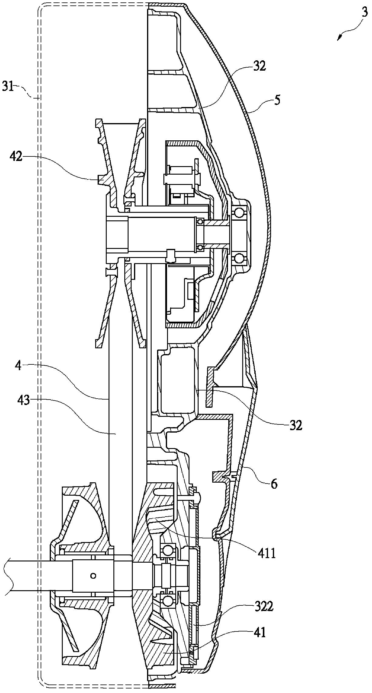
[0018] First, see image 3 , 4 As shown, the transmission box 3 of the present invention has a box body 31 and a cover body 32. The box body 31 and the cover body 32 define an accommodating space, whereby the transmission box 3 can be used for belt transmission. The mechanism 4 is installed. The belt speed change mechanism 4 has a drive disc group 41 and a passive disc group 42. A V-shaped drive belt 43 is interposed between the drive disc group 41 and the passive disc group 42; wherein, the belt speed change mechanism The driving disc group 41 of 4 is driven by the crankshaft of the engine (not shown in the figure). The driving disc group 41 is provided with a centrifugal fan 411 adjacent to the cover 32, and the cover 32 is opened corresponding to the centrifugal fan 411 There is a cooling ...


PUM


Abstract

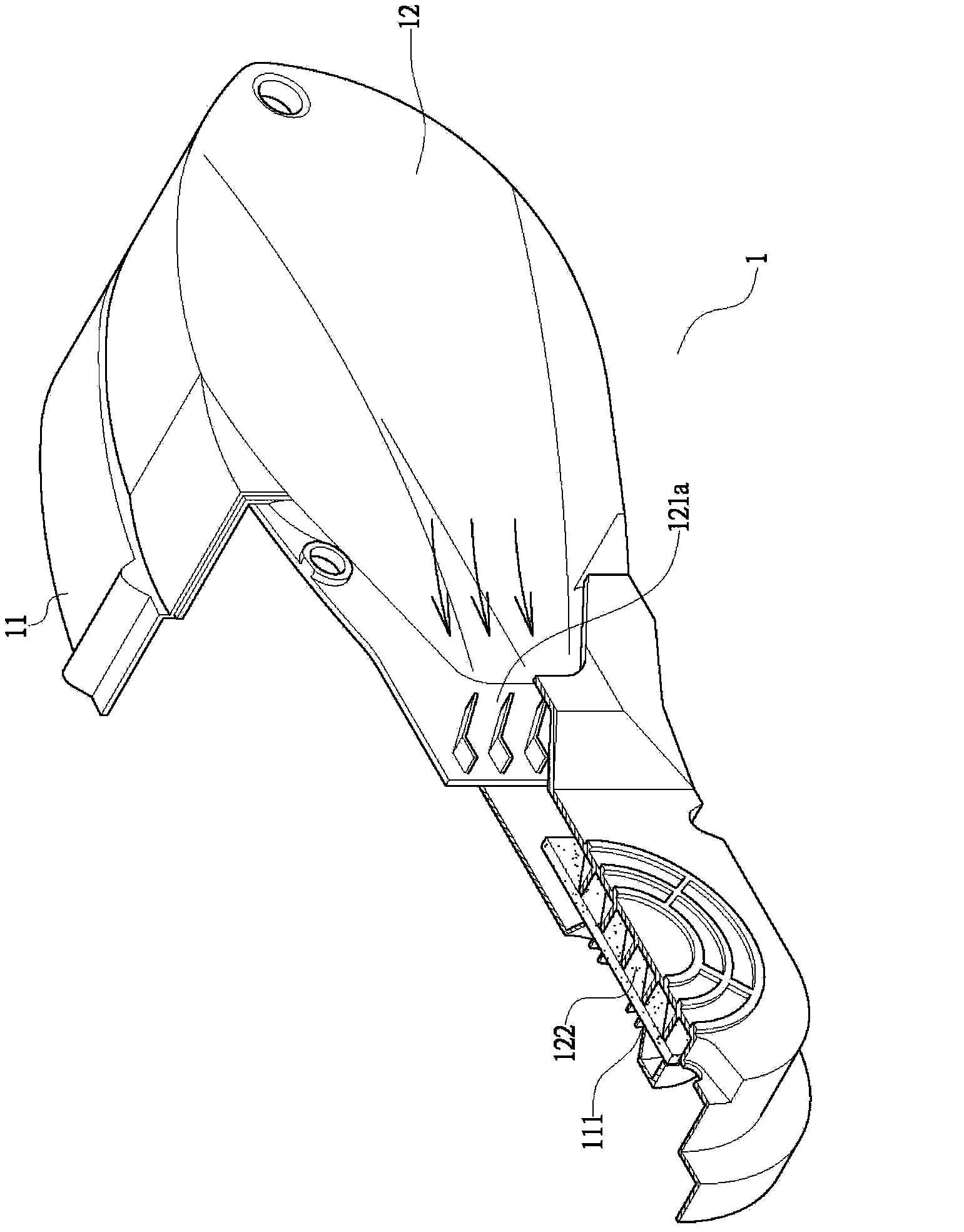
The invention relates to an air deflecting structure for cooling air of a vehicle transmission case. The transmission case is provided with a case body, a cover body and a belt speed changing mechanism, wherein a driving disc set and a driven disc set are arranged on the belt speed changing mechanism; a driving belt is arranged between the driving disc set and the driven disc set; a cooling air inlet is formed in the cover body; an air deflecting hood covers the outer side of the cover body and is at least provided with an air deflecting opening; the air deflecting opening penetrates through the air deflecting hood. The air deflecting structure is characterized in that a current guiding element is convexly arranged near to the air deflecting opening, on the inner side of the air deflecting hood; a covering rib is arranged above the air deflecting opening, on the inner side of the air deflecting hood; the current guiding element and the covering rib form an air guiding opening communicated with the air deflecting opening, on the inner side of the air deflecting hood; a drainage rib corresponding to the current guiding opening is arranged on the inner side of the air deflecting hood; a water draining groove is formed in the lower end of the drainage rib, so that the quantity, entering the transmission case, of water can be effectively reduced, and further the belt speed changing mechanism arranged in the transmission case is enabled to normally work, and the use efficiency of the belt speed changing mechanism of the transmission case can be improved.

Description

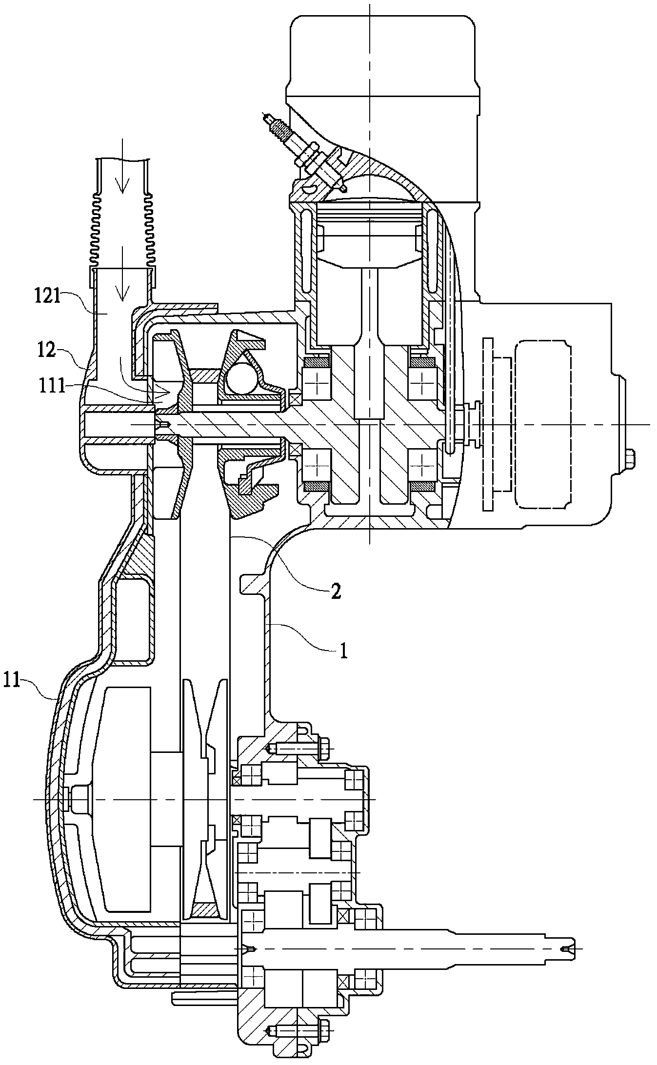
Technical field [0001] The present invention relates to a wind guide structure for cooling wind of a vehicle transmission box, in particular to a provision that can prevent external moisture from entering the transmission box, thereby ensuring the normal operation of the belt transmission mechanism provided in the transmission box, and enabling The wind guiding structure of the cooling wind of the vehicle transmission case improves the use efficiency of the belt transmission mechanism of the transmission case. Background technique [0002] Such as figure 1 As shown, the transmission case 1 of the vehicle power unit is equipped with a belt transmission mechanism 2 which is connected to the transmission case 1 for high-speed operation, thereby moving the vehicle forward. [0003] See again figure 1 As shown, in order to avoid the high temperature generated by the high-speed operation of the belt transmission mechanism 2 in the transmission box 1, damage to the belt transmission mecha...

Claims


Application Information

Patent Timeline
Patent Type & Authority Applications(China)
IPC IPC(8): F16H57/04F16H57/027
CPCF16H57/031F16H57/0416F16H57/0489
Inventor 郑温坐曾新安
Owner KYMCO
Learn More