Sensor unit, electronic apparatus, and moving object

A sensor unit, inertial sensor technology, applied in the field of moving objects, can solve problems such as inertial sensor detection, output characteristic influence, etc.

Active Publication Date: 2015-02-11
SEIKO EPSON CORP
View PDF12 Cites 11 Cited by
  • Summary
  • Abstract
  • Description
  • Claims
  • Application Information

AI Technical Summary

Problems solved by technology

Specifically, vibration may be transmitted to the drive unit of the vibration-type angular velocity sensor or the movable body of the acceleration sensor, thereby affecting the detection and output characteristics of the inertial sensor.

Method used


Image

  • Sensor unit, electronic apparatus, and moving object
  • Sensor unit, electronic apparatus, and moving object
  • Sensor unit, electronic apparatus, and moving object

Examples


Embodiment approach

[0037] Hereinafter, embodiments of the present invention will be described with reference to the drawings.

[0038] Structure of the sensor unit

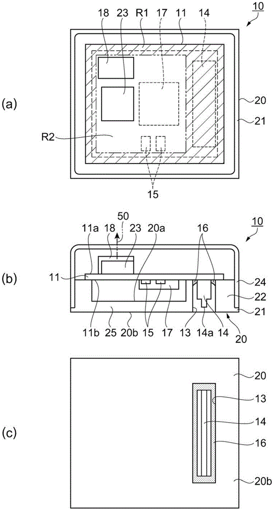
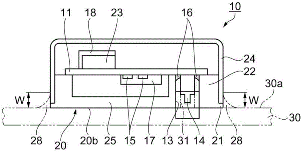
[0039] figure 1 is a diagram schematically showing the appearance of a sensor unit according to an embodiment, and figure 1 (a) is a top view, figure 1 (b) Main sectional view, figure 1 (c) is a bottom view. In addition, in figure 1 In (a), the cover which is a cover member is abbreviate|omitted for the convenience of a view.

[0040] Such as figure 1 As shown, the sensor unit 10 includes: a substrate 11, on which a first sensor device 23 as an inertial sensor, and a connector 14 connected to the first sensor device 23; The opening 13 where the device 14 is exposed. In addition, a cover 24 connected to the holder 20 and serving as a cover member covering the substrate 11 is also provided. The first sensor device 23 is provided at a position overlapping with a gap provided between the substrate 11 and the holder 20 in plan v...


PUM


Abstract

A sensor unit includes a substrate provided with a first sensor device as an inertia sensor and a connector connected to the first sensor device, and a mount on which the substrate is placed and which includes an opening through which the connector is exposed. A gap is provided between the substrate and the mount, and the first sensor device is provided in a position that falls within the gap in a plan view.

Description

technical field [0001] The present invention relates to a sensor unit, electronic equipment including the sensor unit, and a mobile body. Background technique [0002] Conventionally, for example, a sensor module disclosed in Patent Document 1 is known in which a vibration-type angular velocity sensor for vibrating a driving part is mounted on a circuit board supported by a stand, and a sensor module provided with a movable body. Inertial sensors such as acceleration sensors, electronic components such as connectors, and circuit boards and electronic components are covered with cover members. In this sensor module, the connector is exposed from an opening provided on the side surface of the cover member. The electrical connection between the mounting board (control circuit) of the electronic device on which the sensor module is mounted and the sensor module is realized by a connecting member such as a cable or a flexible wiring board extending from a mated connector. [00...

Claims


Application Information

Patent Timeline
Patent Type & Authority Applications(China)
IPC IPC(8): G01C19/56G01P15/02G01P15/18
CPCG01P15/02G01P1/023
Inventor 斋藤佳邦木下裕介小林祥宏佐久间正泰
Owner SEIKO EPSON CORP
Why Eureka
Try Eureka