Magnetic resonance gradient field stimulation level calculating method and apparatus, and magnetic resonance gradient field control method and system
A technology of stimulation level and calculation method, which is applied in magnetic resonance measurement, medical science, sensors, etc., can solve the problems of low efficiency and precision of magnetic resonance gradient field stimulation level, achieve the goals of reducing influence, improving monitoring quality, and improving computing efficiency Effect
- Summary
- Abstract
- Description
- Claims
- Application Information
AI Technical Summary
Problems solved by technology
Method used
Image
Examples
Embodiment 1
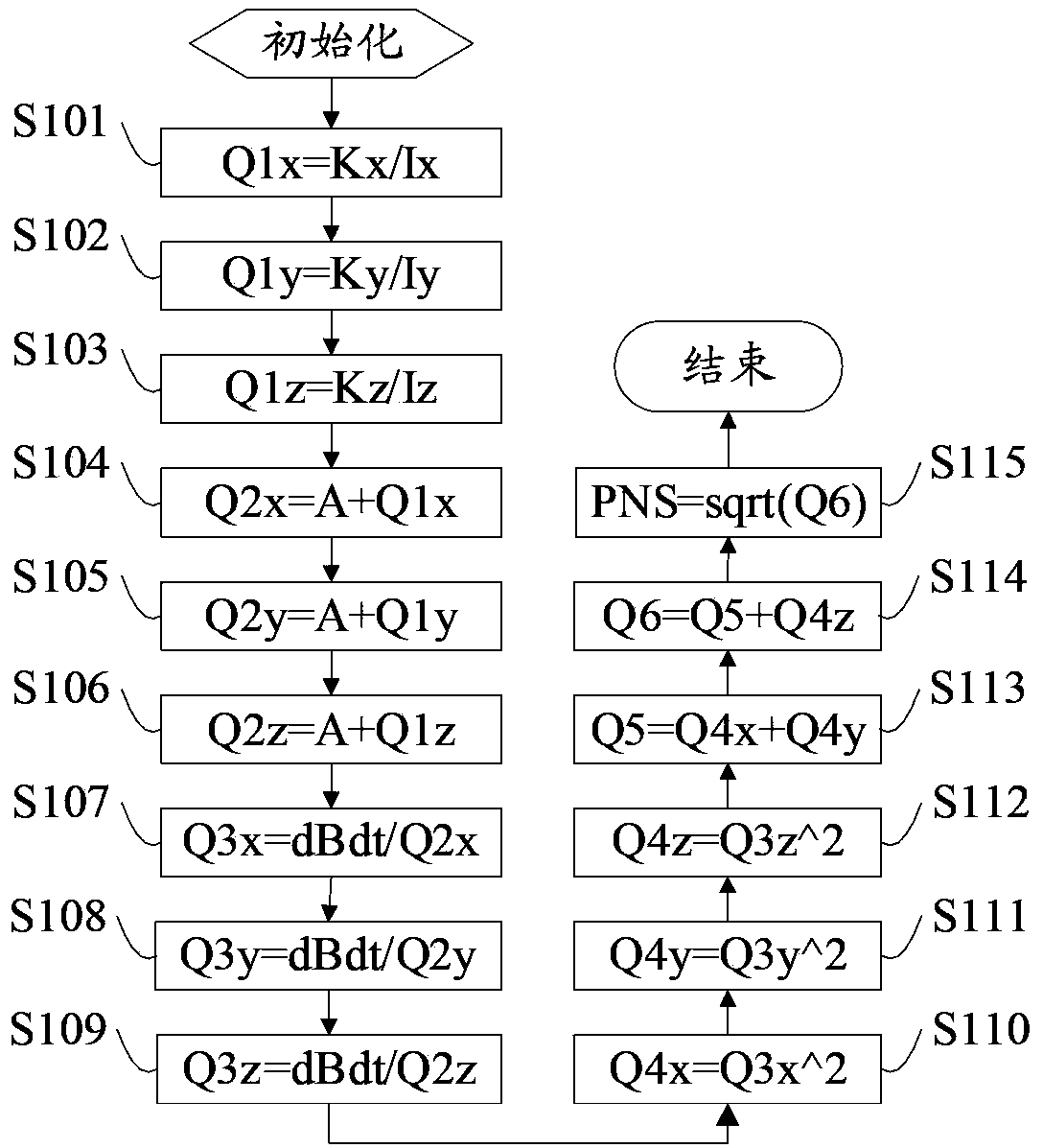
[0086] This embodiment provides a method for calculating the magnetic resonance gradient field stimulation level, using FPGA to calculate the magnetic resonance gradient field stimulation level.
[0087] The magnetic resonance gradient field includes three mutually perpendicular gradient fields, which are respectively the first direction, the second direction and the third direction gradient field. For the convenience of description, in the embodiment of the present invention, the X-axis, Y-axis, and Expressed in the form of the Z axis. It can be understood that, the first, second and third directions and the X-axis, Y-axis and Z-axis can also adopt other corresponding relationships, or the first, second and third directions can also be used In other ways, as long as it can represent three mutually perpendicular gradient fields.
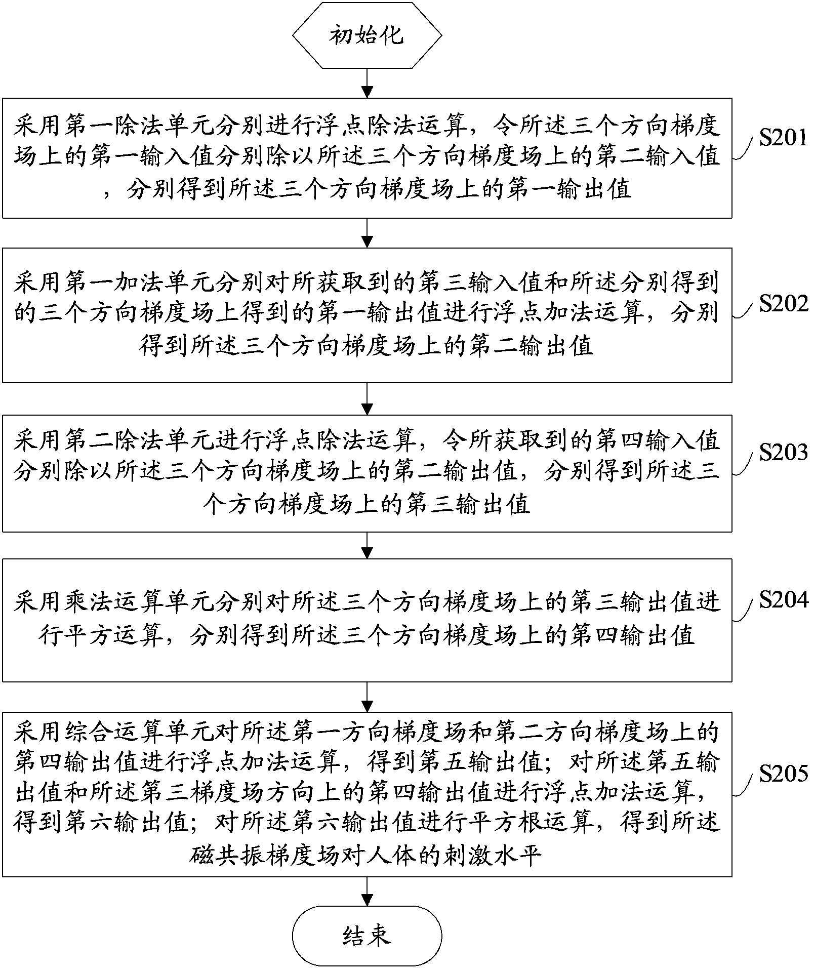
[0088] refer to figure 2 The flow chart of the method for calculating the magnetic resonance gradient field stimulation level is shown, and the m...
Embodiment 2
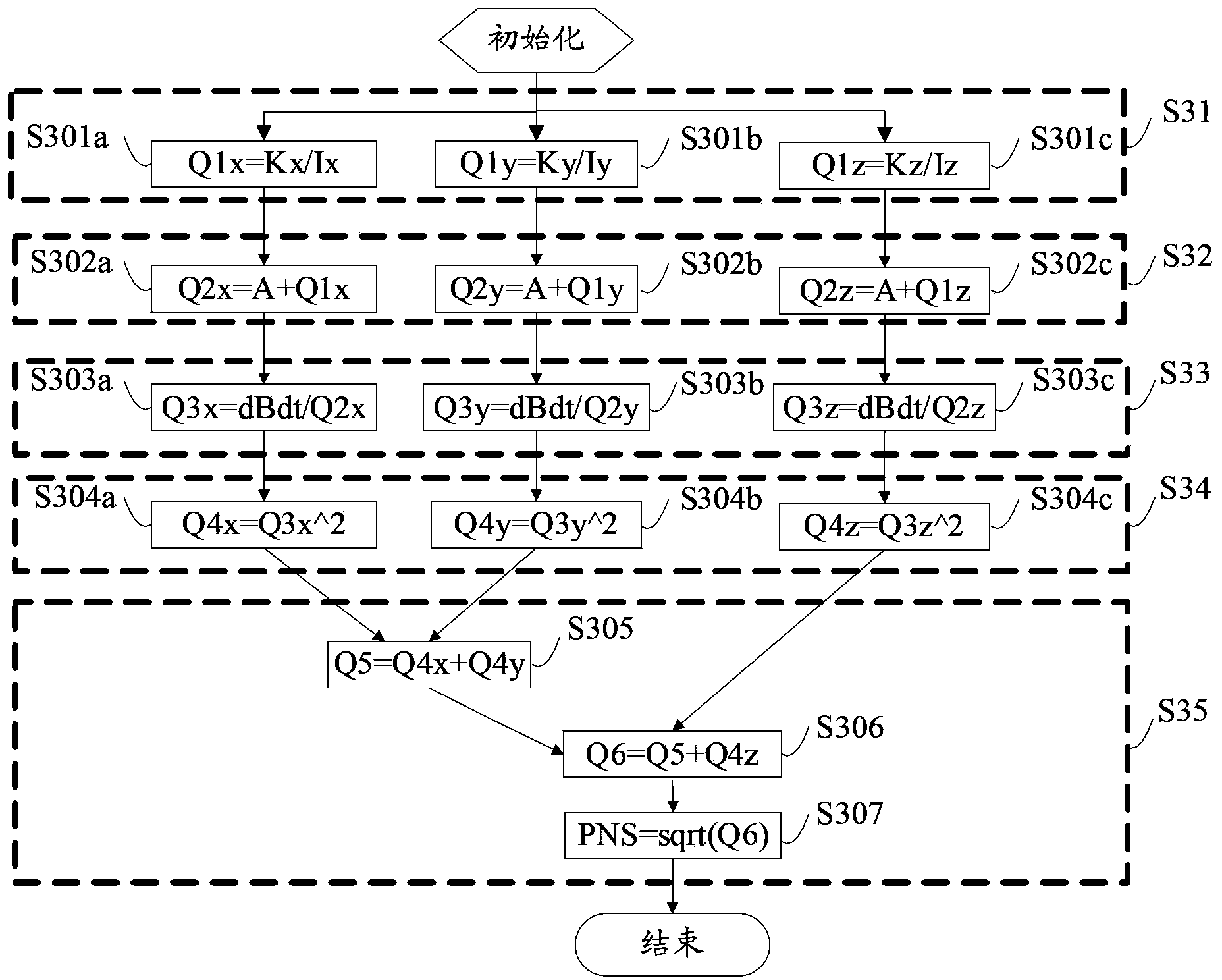
[0106] Each computing unit may include devices that operate independently, and adopt corresponding computing methods for the data on the gradient field in the corresponding direction. The following combination image 3 Describe in detail through specific steps. The multiple steps in the same dotted box indicate that these steps are executed synchronously, as follows:
[0107] S31, steps S301a, S301b and S301c are executed synchronously.
[0108]Specifically, the first dividing unit may include three mutually independent first, second and third dividers, respectively performing parallel floatation on the first input value and the second input value on the gradient field in one direction. point division operation, each obtains the first output value on the gradient field corresponding to the direction. For example, the first divider carries out floating-point division operation to the first input value Kx and the second input value Ix on the gradient field in the X-axis direct...
Embodiment 3
[0119] As mentioned above, each computing unit may also adopt a time-division multiplexing method for operations on the gradient fields in the three directions. refer to image 3 and Figure 4 ,in image 3 The multiple steps in the same dotted box in , indicate that these steps are performed by the same device, and the specific steps are described in detail below:
[0120] S31, time division multiplexing is adopted, and steps S301a, S301b and S301c are executed sequentially.
[0121] Specifically, the first division unit is a seventh divider, which adopts a time-division multiplexing method, and the seventh divider sequentially performs the first input value and the second input value obtained on the gradient fields of the three directions. Floating-point division operation, sequentially obtain the first output value on the gradient field of the three directions, such as Figure 4 As shown, after the two input terminals of the seventh divider input Kx / Ky / Kz and Ix / Iy / Iz re...
PUM
 Abstract
Description
Claims
Application Information
 - R&D
- Intellectual Property
- Life Sciences
- Materials
- Tech Scout
- Unparalleled Data Quality
- Higher Quality Content
- 60% Fewer Hallucinations
Browse by: Latest US Patents, China's latest patents, Technical Efficacy Thesaurus, Application Domain, Technology Topic, Popular Technical Reports.
© 2025 PatSnap. All rights reserved.Legal|Privacy policy|Modern Slavery Act Transparency Statement|Sitemap|About US| Contact US: help@patsnap.com


