
Ground potential installation type shunt clamp device and installation method thereof
A technology of shunt line and ground potential, which is applied in the direction of cable installation, overhead installation, electrical components, etc., and can solve problems such as inability to carry out, fail to reach a safe distance, miscellaneous tools, etc.
- Summary
- Abstract
- Description
- Claims
- Application Information
AI Technical Summary
Problems solved by technology
Method used
Image

Examples
Embodiment Construction
[0020] The present invention will be further described in detail below in conjunction with the drawings and specific embodiments.
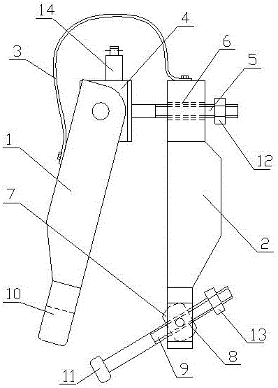
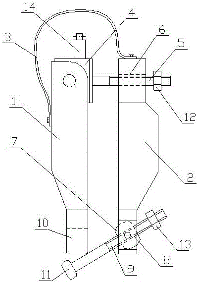
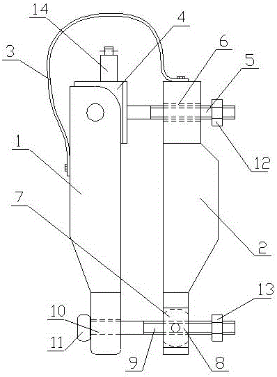
[0021] The ground potential installation type shunt clamp device of the present invention, such as figure 1 As shown, it includes two wire clips 1, 2 on the left and right sides, and a drainage wire 3 connecting the two wire clips. The upper end of the left wire clip 1 is connected to a bracket 4, and the bracket 4 is fixedly connected to the right with a The upper end of the first bolt 5 and the right clamp 2 is provided with a through hole 6 having a diameter larger than that of the first bolt 5 and is sleeved on the first bolt 5. A rotating block 7 is hinged on the lower end of the right-side wire clamp 2. The rotating block 7 is provided with a threaded through hole 8 and a second bolt 9 is penetrated, so that the second bolt 9 can swing around with the rotation speed 7 or with the right The side clamp 2 rotates around the first bolt 5. A bayone...
PUM
 Abstract
Description
Claims
Application Information