
Channel measuring method for large-scale antennas, and user terminal

A large-scale antenna and channel measurement technology, applied in channel estimation, wireless communication, diversity/multi-antenna systems, etc.

Active Publication Date: 2015-02-11
HUAWEI TECH CO LTD
View PDF7 Cites 7 Cited by
  • Summary
  • Abstract
  • Description
  • Claims
  • Application Information

AI Technical Summary

Problems solved by technology

In this way, the same pilot signal is sent on the antennas in the group. Although the pilot overhead caused by multiple antennas can be saved, the pilot receiving end cannot perform complete channel measurement.

Method used


Image

  • Channel measuring method for large-scale antennas, and user terminal
  • Channel measuring method for large-scale antennas, and user terminal
  • Channel measuring method for large-scale antennas, and user terminal

Examples


Embodiment Construction

[0057] In order to make the object, technical solution and advantages of the present invention clearer, the present invention will be described in detail below in conjunction with the accompanying drawings and specific embodiments.

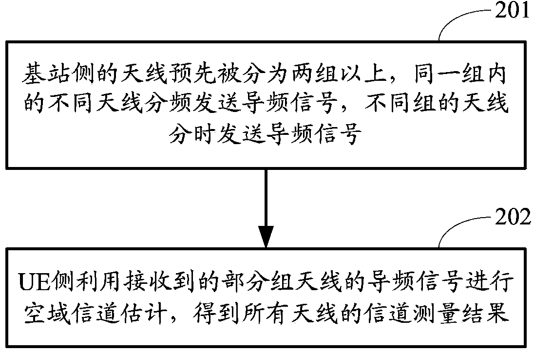
[0058] The method provided by the embodiment of the present invention is as figure 2 As shown, it mainly includes the steps on both sides, that is, the steps on the base station side and the terminal side:

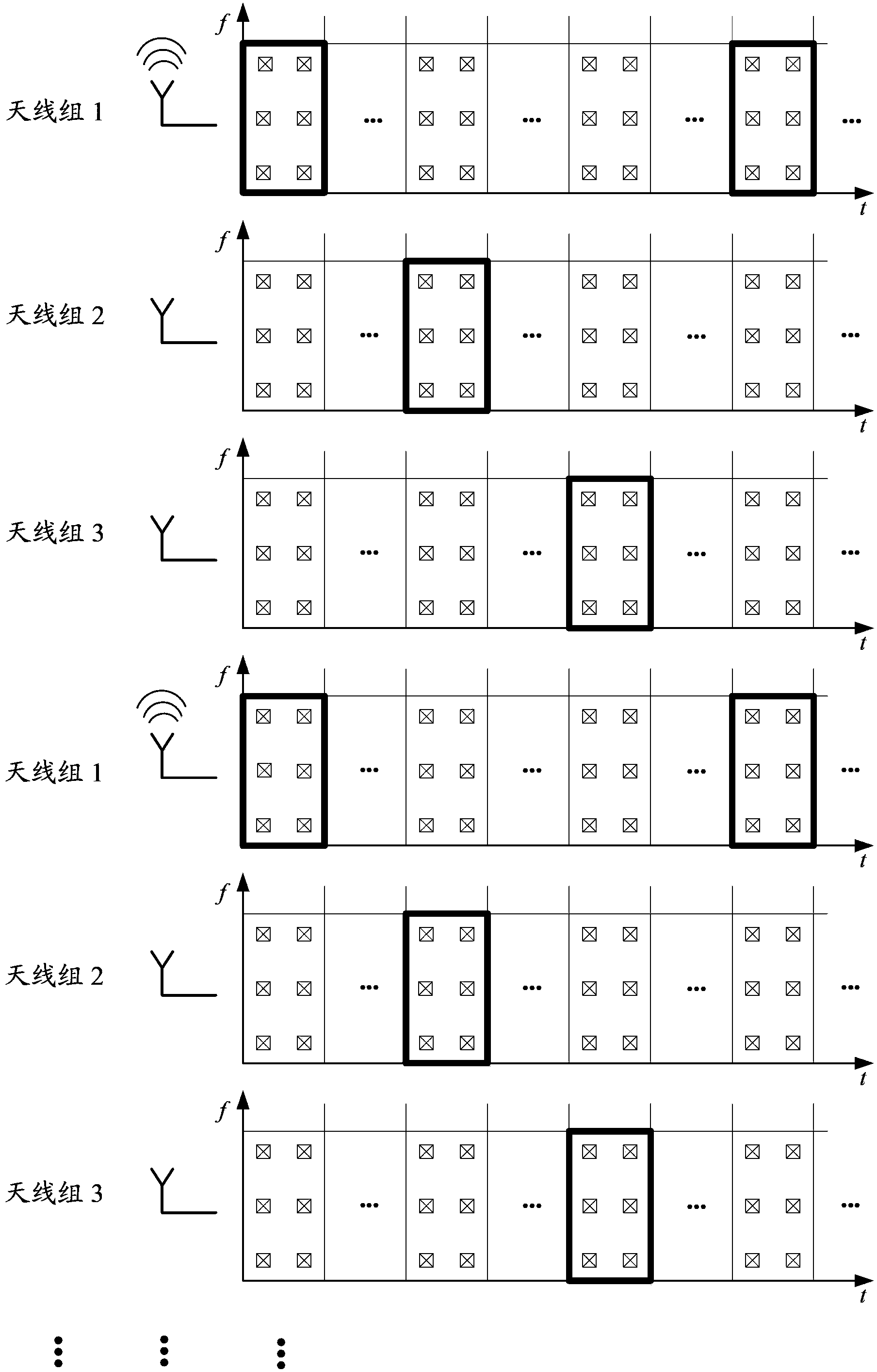
[0059] Step 201: The antennas on the base station side are divided into two or more groups in advance, different antennas in the same group transmit pilot signals in frequency division, and antennas in different groups transmit pilot signals in time division.

[0060] Step 202: The UE side uses the received pilot signals of some groups of antennas to perform spatial channel estimation, and obtains channel measurement results of all antennas.

[0061] Each step will be described in detail below in conjunction with the embodiments. Assuming t...


PUM


Abstract

Provided are a channel measurement method for large-scale antennas, and a user terminal. The method comprises: pre-dividing antennas at a base station side into more than two groups, and a user terminal receiving pilot signals which are sent by different antennas in the same group at the base station side by adopting a frequency division manner and antennas in different groups by adopting a time division manner; and using the received pilot signals of some groups of antennas to conduct airspace channel estimation, so as to obtain channel measurement results of all the antennas. The present invention can ensure the integrity of channel measurement while reducing the pilot overhead. In addition, the user terminal has no need to conduct airspace channel estimation after waiting to receive the pilot signals of all groups of antennas, thereby reducing the time delay of channel parameter feedback.

Description

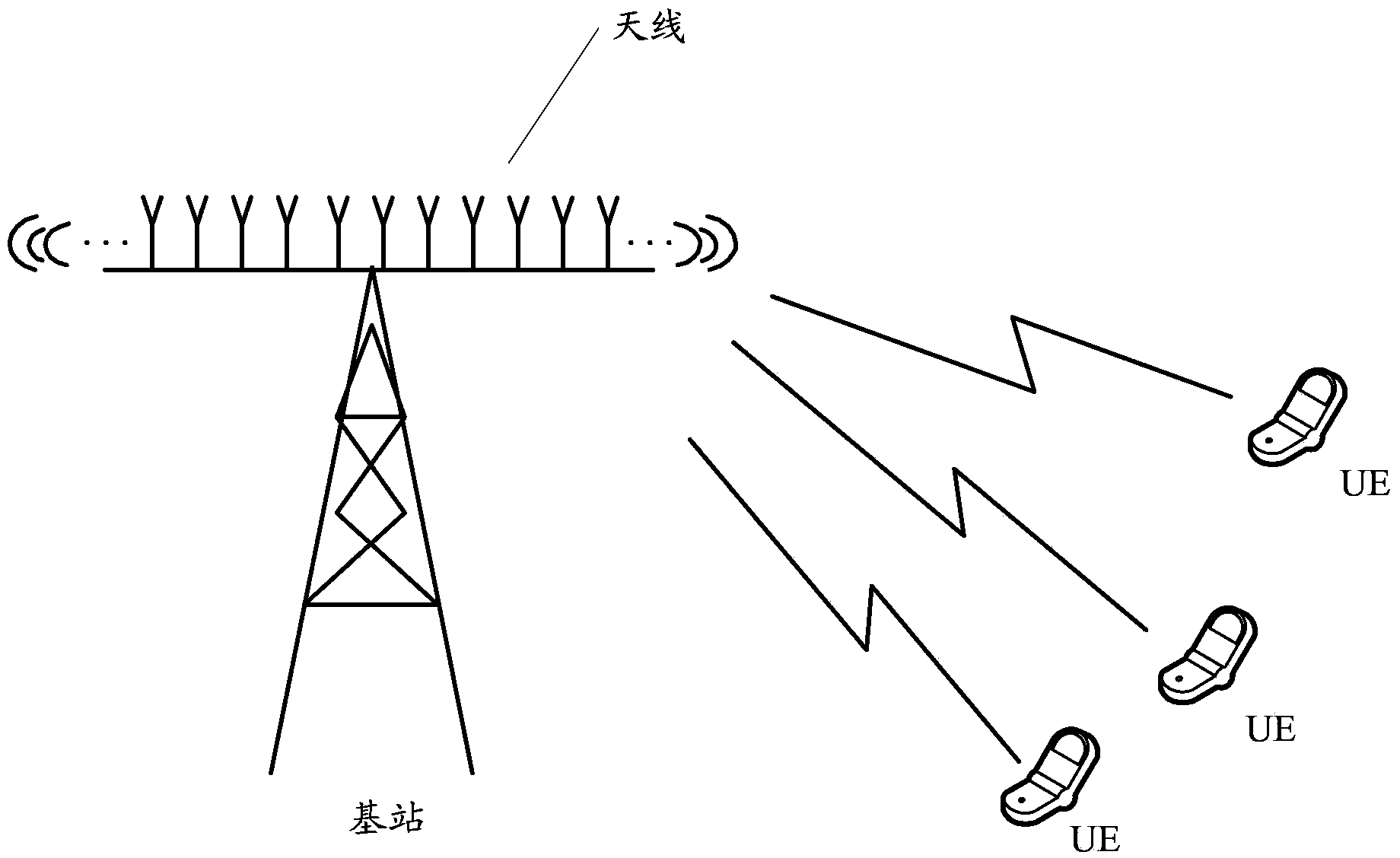
【Technical field】 [0001] The invention relates to the technical field of wireless communication, in particular to a channel measurement method for a large-scale antenna and a user terminal. 【Background technique】 [0002] Improving system throughput is the main goal of the next-generation cellular communication system, and the MIMO (Multiple-Input-Multiple-Output) method is an important way to achieve this goal in modern mobile communications. Massive antennas are a further extension of MIMO technology, which improves system throughput by deploying a large number of antennas on the base station side, such as figure 1 shown. [0003] In a MIMO system, the base station needs to send pilot signals to the entire cell at intervals, and the UE (user terminal) in the cell uses the pilot to perform channel measurement for the calculation of channel parameters such as CQI (channel state indication) and feedback to the base station . Due to the small number of transmitting antennas...

Claims


Application Information

Patent Timeline
IPC IPC(8): H04L25/02H04L5/00
CPCH04B7/04H04L27/26H04L25/0228H04B7/0417H04B7/0619H04L5/0023H04L5/0048H04L25/0204H04L25/0226H04W24/02
Inventor 王磊
Owner HUAWEI TECH CO LTD
Learn More