
Fluid-dynamic device and fuel feed system comprising said fluid-dynamic device

A fuel supply system, fluid dynamics technology, applied in the direction of charging system, liquid fuel feeder, fuel injection pump, etc., can solve the problems of incomplete solution, opening, etc., and achieve the effect of reducing workload and reducing fuel consumption

Inactive Publication Date: 2015-02-11
ROBERT BOSCH GMBH
View PDF6 Cites 0 Cited by
  • Summary
  • Abstract
  • Description
  • Claims
  • Application Information

AI Technical Summary

Problems solved by technology

[0012] The disadvantage of this solution is that the inlet valve opens at a lower pressure than the opening pressure of the overflow valve, so this solution does not completely solve the above-mentioned disadvantages

Method used


Image

  • Fluid-dynamic device and fuel feed system comprising said fluid-dynamic device
  • Fluid-dynamic device and fuel feed system comprising said fluid-dynamic device
  • Fluid-dynamic device and fuel feed system comprising said fluid-dynamic device

Examples


Embodiment Construction

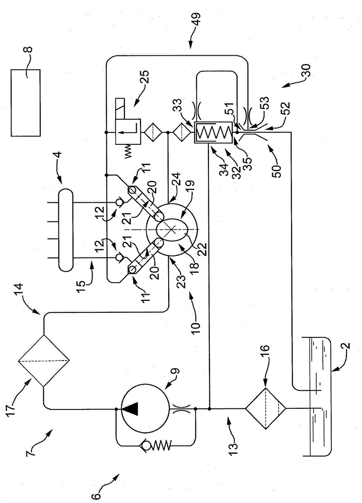
[0029] refer to figure 1 , reference numeral 1 denotes a system for supplying fuel from a fuel tank to an internal combustion engine.

[0030] refer to figure 1 , reference numeral 1 designates in its entirety a system for feeding fuel (diesel fuel in the case in question) from a fuel tank 2 to an internal combustion engine of known type (not shown).

[0031] In more detail, the internal combustion engine is a diesel engine comprising a manifold 4 for distributing fuel (commonly called "common rail") and a series of electrically operated injectors (not shown), said manifold Designed to accommodate fuel with a pressure preferably (but not necessarily) greater than 1800 bar; said injectors are directly connected to the common rail 4 and are operable to dissipate the fuel mist in each combustion chamber of an internal combustion engine (not shown) change.

[0032] refer to figure 1 The fuel supply system 1 generally comprises a fuel pump unit 6, a hydraulic circuit 7, and a c...


PUM


Abstract

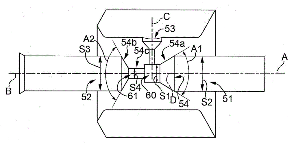
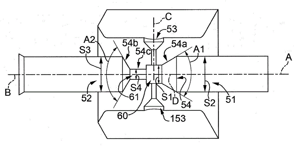
Fluid-dynamic device for a fuel feed system; the fluid-dynamic device (50) comprising an inlet conduit (51) extending along an axis (A), an outlet conduit (52) extending along the axis (A), an intake conduit (53), and a connecting conduit (54) into which the inlet conduit (51), the outlet conduit (52) and the intake conduit (53) converge; the connecting conduit (54) defines a constriction between the inlet conduit (51) and the outlet conduit (52) so that, during use, a fuel pressure is created in the intake conduit (53) lower than the pressure in the inlet conduit (51) and the outlet conduit (52).

Description

technical field [0001] The invention relates to a fluid dynamic device and a fuel supply system comprising the fluid dynamic device. Background technique [0002] In more detail, the fuel supply system is a system for supplying diesel fuel from a fuel tank to a diesel engine, the following description will make specific reference to the application of this system without thereby limiting the general characteristics of this system in any way. [0003] Generally, the fuel supply system includes: [0004] - low pressure pump or front pump; [0005] - high pressure pumps including at least one inlet valve; [0006] - a hydraulic circuit comprising a delivery branch for connecting the pre-pump to the inlet valve of the high-pressure pump; and [0007] - A throttle valve positioned along the delivery branch for supplying a given amount of fuel to the inlet valve. [0008] Furthermore, the hydraulic circuit comprises a drain branch for recovering excess fuel, which drain branch...

Claims


Application Information

Patent Timeline
Patent Type & Authority Applications(China)
IPC IPC(8): F02M59/34F02M63/00F02M37/02F02M37/00
CPCF02M37/0052F02M37/0029F02M37/025F02M63/0001F02M59/34
Inventor L·菲奥伦蒂诺
Owner ROBERT BOSCH GMBH
Learn More