Optical fiber drawing and whipping control device

A control device and wire drawing technology, which is applied in manufacturing tools, glass manufacturing equipment, glass production, etc., can solve problems such as fiber damage, fiber breakage, and fiber waste, and achieve the effects of reducing whiplash, prolonging service life, and reducing waste

Active Publication Date: 2015-02-18
ZHONGTIAN TECH FIBER OPTICS +2
View PDF3 Cites 13 Cited by
  • Summary
  • Abstract
  • Description
  • Claims
  • Application Information

AI Technical Summary

Problems solved by technology

At present, the take-up speed has reached more than 2000m / min. During high-speed switching, due to the high speed, the take-up reel brakes at high speed after switching, and the broken end of the fiber will be whipped on the surface of the fiber, causing damage to the fiber.
Press the optical fiber with the pressure rod and pull it into the cutting groove. After the switching is successful, due to the high speed, the broken end of the optical fiber will be whipped on the surface of the optical fiber, causing the fiber to be broken when the optical fiber is rewound, resulting in a waste of optical fiber

Method used


Image

  • Optical fiber drawing and whipping control device
  • Optical fiber drawing and whipping control device
  • Optical fiber drawing and whipping control device

Examples


Embodiment Construction

[0021] In order to make the purpose, technical solution and advantages of the present invention clearer, the following will further describe the implementation of the present invention in detail in conjunction with the accompanying drawings.

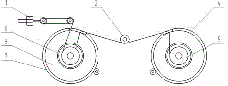
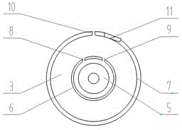
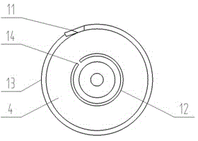
[0022] In the operation of the traditional wire drawing take-up machine, the optical fiber will be pressed by the pressure rod and drawn into the cutting groove. After the switching is successful, due to the high speed, the broken end of the optical fiber will be whipped on the surface of the optical fiber, causing the optical fiber to be damaged when the optical fiber is rewound. Fiber will be broken, resulting in waste of optical fiber. In order to better solve this problem, an optical fiber drawing whip control device as described in the present invention is designed. It is mainly to provide an automatic control system and control method for reducing whiplash in the process of wire drawing switching. It is an automatic control system ...


PUM

PropertyMeasurementUnit
diameteraaaaaaaaaa
diameteraaaaaaaaaa

Abstract

The invention provides an optical fiber drawing and whipping control device comprising a flat cable arm sensor, a compression bar wheel, a whipping ring A and a whipping ring B, wherein the whipping ring A and the whipping ring B are the same in structure and are arranged on the same horizontal straight line by virtue of a mirror image distribution center point; an optical fiber disc is arranged in each of the whipping ring A and the whipping ring B; the flat cable arm sensor is arranged above the whipping ring A; and the compression bar wheel is fixedly arranged between the whipping ring A and the whipping ring B. After switching, optical fibers are swung outside the optical fiber disc, so that whipping cannot be performed on the surface of the optical fiber disc, and thus the optical fiber whipping is effectively reduced. According to the optical fiber drawing whipping control device, the inner diameter of each of an anti-whipping ring washer A and an anti-whipping ring washer B is 2-6mm greater than that of the optical fiber disc, and after switching, the optical fibers are swung outside the optical fiber disc and a protection cover, and the optical fiber disc can be normally operated in the anti-whipping ring washer A and the anti-whipping ring washer B.

Description

technical field [0001] The invention relates to optical fiber production equipment, in particular to an optical fiber drawing whipping control device. Background technique [0002] Optical fiber, short for optical fiber, is a fiber made of glass or plastic that acts as a means of light transmission. The principle of transmission is 'total reflection of light'. Kao Kung, former president of the Chinese University of Hong Kong, and George A. Hockham first proposed the idea that optical fibers could be used for communication transmission, for which Kao Kung won the 2009 Nobel Prize in Physics. In daily life, optical fibers are used for long-distance information transmission because the loss of light in optical fibers is much lower than that of electricity in wires. [0003] In the multimode optical fiber, the diameter of the core is two kinds of 50 μm and 62.5 μm, which are roughly equivalent to the thickness of a human hair. The diameter of the single-mode fiber core is...

Claims


Application Information

Patent Timeline
Patent Type & Authority Applications(China)
IPC IPC(8): C03B37/03
CPCY02P40/57C03B37/07C03B37/032
Inventor 张帆江金金朱刘盅薛驰刘志忠曹珊珊
Owner ZHONGTIAN TECH FIBER OPTICS
Why Eureka
Try Eureka