Design method of counter flow cooling tower

A design method and technology of cooling towers, applied in the direction of calculation, special data processing applications, instruments, etc., can solve the problems of increasing energy consumption of towers, uneven water distribution, deviation of packing system from design values, etc., and achieve energy saving and calculation accuracy. high effect

Inactive Publication Date: 2015-02-18
GUANGZHOU METRO GRP CO LTD
View PDF0 Cites 9 Cited by
  • Summary
  • Abstract
  • Description
  • Claims
  • Application Information

AI Technical Summary

Problems solved by technology

[0004] Since the relative humidity of the air out of the tower deviates from the design conditions, it is impossible to ensure that the relative humidity is maintained at 95% to 100%. These are the keys to analyze the influence of the cooling tower air outlet on the surrounding thermal environment; in addition, the Lewis relation is often used in the calculation, and this relation is derived under the condition of equal enthalpy humidification, which is not necessarily necessary for the calculation and design of the cooling tower. This relation is applicable; after the tower has been in operation for a period of time, the packing system deviates from the design value due to packing damage and uneven water distribution; after the deviation, the cooling effect of the tower becomes worse and the cooling capacity decreases. To ensure the same heat dissipation, only add Large air volume and water flow, thus increasing the energy consumption of the tower

Method used


Image

  • Design method of counter flow cooling tower
  • Design method of counter flow cooling tower
  • Design method of counter flow cooling tower

Examples


Embodiment Construction

[0022] The present invention will be described in detail below with reference to the accompanying drawings and specific implementation methods. The schematic implementation and description of the present invention are used to explain the present invention, but are not intended to limit the present invention.

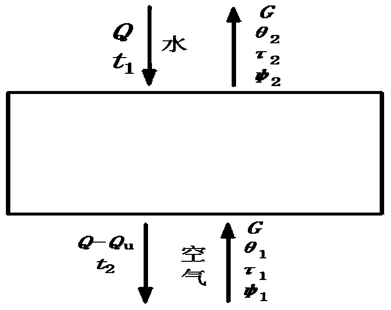
[0023] figure 1 It is the calculation principle of the countercurrent tower in this design method. figure 1 , the cooling water inlet flow is Q, and the cooling water outlet flow is Q-Q u (Q u is the evaporative amount of cooling water), the inlet water temperature t 1 , the outlet water temperature t 2 , inlet air flow G, inlet air dry bulb temperature θ 1 , the outlet air dry bulb temperature θ 2 , the intake wet bulb temperature τ 1 , the outlet air wet bulb temperature τ 2 , ψ 1 The relative humidity of the air entering the tower, ψ 2 The relative humidity of the air out of the tower. The movement of water and air in the countercurrent tower can be regarded...


PUM


Abstract

The invention relates to a design method of a counter flow cooling tower. The method comprises the following steps: 1, setting the Lewis number to be 1 and correcting a Lewis relation formula; 2, correcting the performance number N of the cooling tower by a correction coefficient k2; 3, iteratively calculating according to the steps 1 and 2 and a formula described in the specifications to obtain the outlet water temperature of the counter flow cooling tower; 4, iteratively calculating by a formula described in the specifications according to the same line relationship of state points of air entering and exiting from the tower and state points of atmosphere on a psychrometric chart to obtain the moisture content of the air exiting from the tower; 5, iteratively calculating according to a reflux ratio formula to obtain the enthalpy value of the air exiting from the tower; 6, obtaining the corrected outlet water temperature and the corrected state parameters of the air entering and exiting from the tower in the counter flow cooling tower which takes the Lewis number and a filler coefficient into account. According to the design method, the Lewis number and the filler coefficient are fully considered during correction and reflux, the calculation precision is very high, a calculation result is matched with an actual measurement result, and the technical problem that the temperature and humidity of the air entering and exiting from the tower cannot be calculated by taking the enthalpy value as the intermediate quantity is solved.

Description

technical field [0001] The invention relates to a design method of a counter-flow cooling tower considering the deviation correction of Lewis number and packing coefficient. Background technique [0002] The cooling tower is an important equipment in the air-conditioning system, and its operating performance will have a direct impact on the heat exchange of the condenser, thereby affecting the operating efficiency of the entire air-conditioning system. [0003] For mechanical ventilation cooling towers, the traditional design method has great limitations, and the calculated results of the traditional design method deviate greatly from the measured results. For example, the enthalpy value is used as the intermediate variable in the calculation, so it is impossible to accurately solve the temperature and humidity of the cooling tower outlet air. Usually, the relative humidity of the outlet air is assumed to be 95% to 100%, which artificially causes errors. [0004] Since the ...

Claims


Application Information

Patent Timeline
Patent Type & Authority Applications(China)
IPC IPC(8): G06F17/50
Inventor 夏少丹马建荣吴疆罗定鑫冯腾飞蔡博达张瑞冯泽刘昶张波惠咏薇王绍兴邬燕芳吴滔唐艳英高俊霞赵成军刘金平刘雪峰陈星龙罗文海
Owner GUANGZHOU METRO GRP CO LTD
Why Eureka
Try Eureka