Vocal cavity device and voice box

A sound cavity and speaker technology, applied in the field of speaker equipment, can solve problems such as poor sound quality, incomplete presentation of bass, and unsmooth air conduction sound waves, etc., to achieve good acoustic effects

Inactive Publication Date: 2015-02-18
深圳市星盘科技有限公司
View PDF6 Cites 2 Cited by
  • Summary
  • Abstract
  • Description
  • Claims
  • Application Information

AI Technical Summary

Problems solved by technology

[0004] The embodiment of the present invention provides an acoustic cavity device and a sound box, aiming to solve the problem that the existing acoustic cavity is mostly limited

Method used


Image

  • Vocal cavity device and voice box
  • Vocal cavity device and voice box
  • Vocal cavity device and voice box

Examples


Embodiment 1

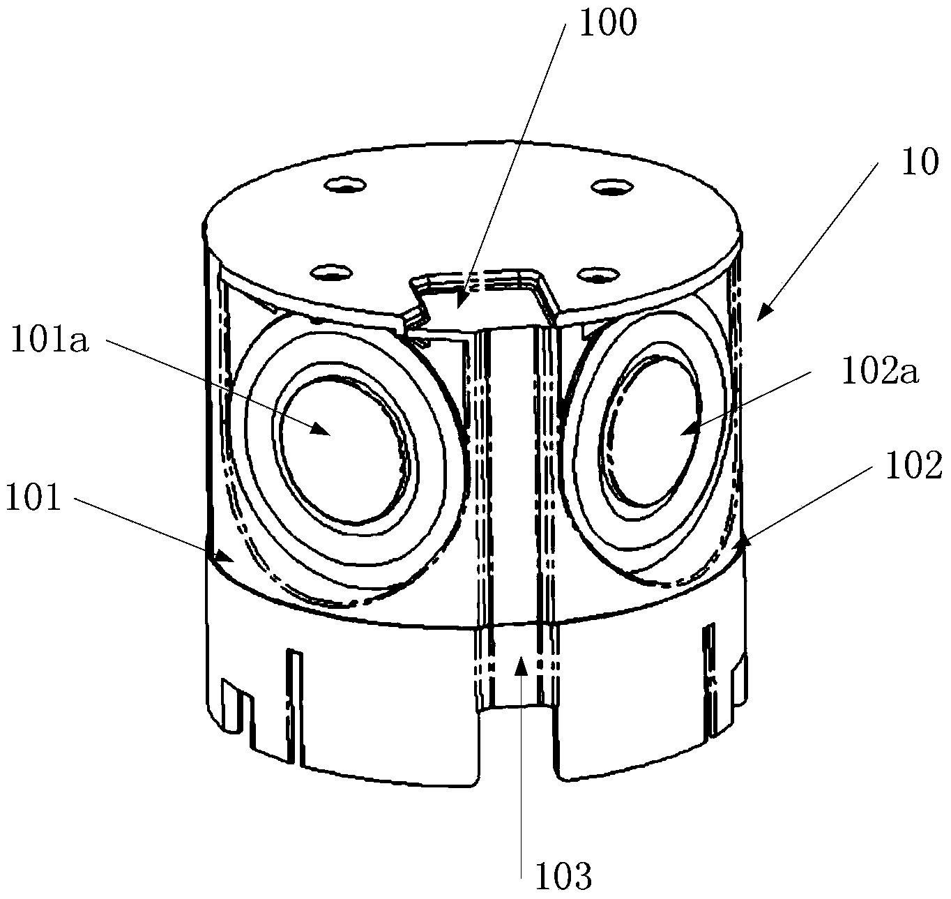
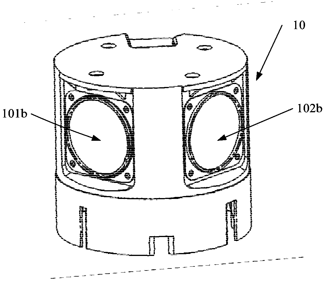
[0023] figure 1 , figure 2 A specific structural block diagram of the acoustic cavity device provided by Embodiment 1 of the present invention is shown, and for convenience of description, only parts related to the embodiment of the present invention are shown. In this embodiment, the acoustic cavity device 10 includes: a cavity 100, a first sound emitting structure 101 and a second sound emitting structure 102, wherein the first sound emitting structure 101 is composed of a speaker 101a and a diaphragm 101b, and the The first sounding structure 102 is made up of a speaker 102a and a diaphragm 102b. Symmetrically arranged, the horn 101a, 102a axes of the first sounding structure 101 and the second sounding structure 112 form an angle less than 180° and are fixed to the cavity by screws, the first sounding structure 101 and the second sounding structure 112 The included angle formed by the axes of the vibrating membranes 101b and 102b of the structure 102 is less than 180°. ...

Embodiment 2

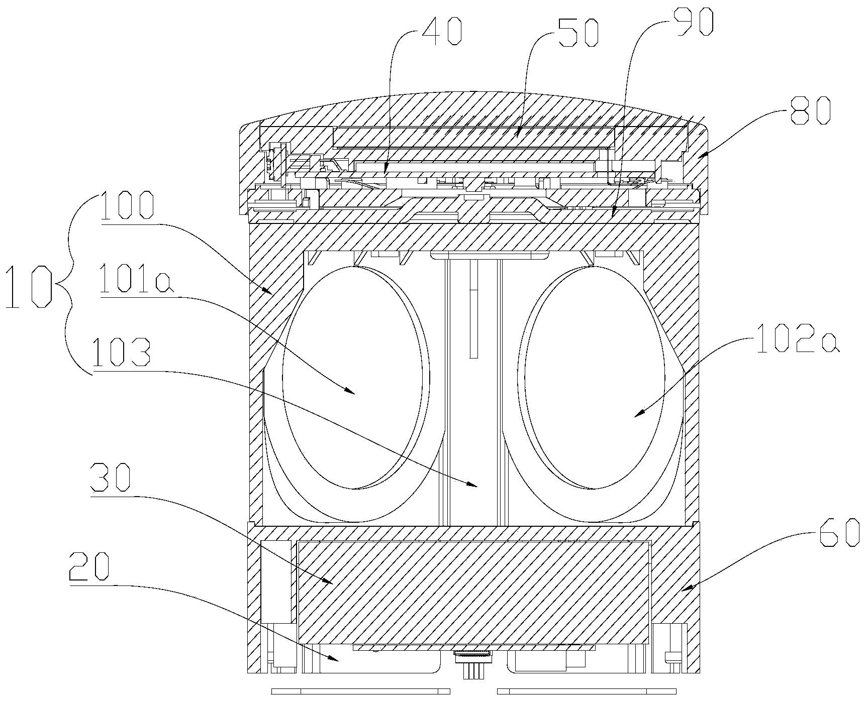
[0027] image 3 , Figure 4 A schematic structural diagram of the sound box provided by Embodiment 2 of the present invention is shown, and for convenience of description, only parts related to the embodiment of the present invention are shown. In this embodiment, the sound box includes: the acoustic chamber device 10 as described in Embodiment 1, the power supply module 20, the power amplifier control module 30, the display control module 40 and the touch screen 50, and the power supply module 20 and the power amplifier control module 30 are arranged on The bottom of the cavity 100 , the display control module 40 and the touch screen 50 are disposed on the top of the cavity 100 .

[0028] Further, as Figure 5 As shown, it also includes a lower cover 60 arranged on the lower part of the acoustic cavity device 10 , and several fixing grooves 61 are provided on its upper surface, and the lower cover 60 is fixed to the bottom of the acoustic cavity device 10 by screws.

[002...


PUM

PropertyMeasurementUnit
Angleaaaaaaaaaa

Abstract

The invention is applicable to the technical field of voice box equipment, and provides a vocal cavity device and a voice box. The vocal cavity device comprises a cavity, a first voice production structure and a second voice production structure, each of the first and second voice production structures is composed of a loudspeaker and a vibrating diaphragm, the loudspeakers and the vibrating diaphragms are arranged on the circumference of the cavity in axial symmetry, an included angle formed by axes of the loudspeakers of the first and second voice production structures is less than 180 degrees, the first and second voice production structures are fixed in the cavity through bolts, and an included angle formed by axes of the vibrating diaphragms of the first and second voice production structures is less than 180 degrees. A plurality of voice production structures are reasonably arranged in the cavity, so that the angle that voice sent by the loudspeakers reaches to a listener is more in line with the acoustical principle, and better acoustic effect is achieved.

Description

technical field [0001] The invention belongs to the technical field of sound box equipment, and in particular relates to an acoustic cavity device and a sound box. Background technique [0002] The speaker is the terminal of the entire audio system, and its function is to convert audio power into corresponding sound energy and radiate it into the space. It is an extremely important part of the audio system, because it is responsible for the key task of converting electrical signals into acoustic signals for human ears to listen directly to. It has to deal directly with human hearing, which is very sensitive. And it has a strong ability to distinguish the timbre of complex sounds. Because the human ear's subjective experience of sound is the most important criterion for evaluating the sound quality of a sound system. [0003] Most of the existing small speakers are a speaker, and the acoustic cavity for the speaker is mostly limited to the narrow space of the acoustic cavit...

Claims


Application Information

Patent Timeline
IPC IPC(8): H04R1/20
Inventor 易虎马泽锋
Owner 深圳市星盘科技有限公司
Why Eureka
Try Eureka