Inclined plane anvil forging connecting rod transition conical face and transition conical face machining method thereof

A transition cone and connecting rod technology, which is applied in the direction of manufacturing tools, metal processing equipment, forging/pressing/hammer devices, etc., can solve the problems of high processing cost, many forging processes, large processing allowance, etc., and achieve short machining cycle , High material utilization rate, good effect of metal flow

Inactive Publication Date: 2015-02-25
武汉重工铸锻有限责任公司
View PDF7 Cites 2 Cited by
  • Summary
  • Abstract
  • Description
  • Claims
  • Application Information

AI Technical Summary

Problems solved by technology

[0003] At present, there is a conical surface in the middle of domestic marine connecting rods. The main production method is to use upper and lower flat anvils, free forging, and use traditional flat anvils to forge larger model connecting rods (50 machines and above models), whether forging or later machining. There are many deficiencies: First, in the forging process, because the flat anvil forging is difficult to forge the middle conical surface, the conical transition area between the two ends of the connecting rod and the middle rod can only be forged into a flat square step, so that the forged connecting rod, The margin

Method used


Image

  • Inclined plane anvil forging connecting rod transition conical face and transition conical face machining method thereof
  • Inclined plane anvil forging connecting rod transition conical face and transition conical face machining method thereof
  • Inclined plane anvil forging connecting rod transition conical face and transition conical face machining method thereof

Examples


Embodiment Construction

[0021] The present invention will be described in detail below with reference to the accompanying drawings.

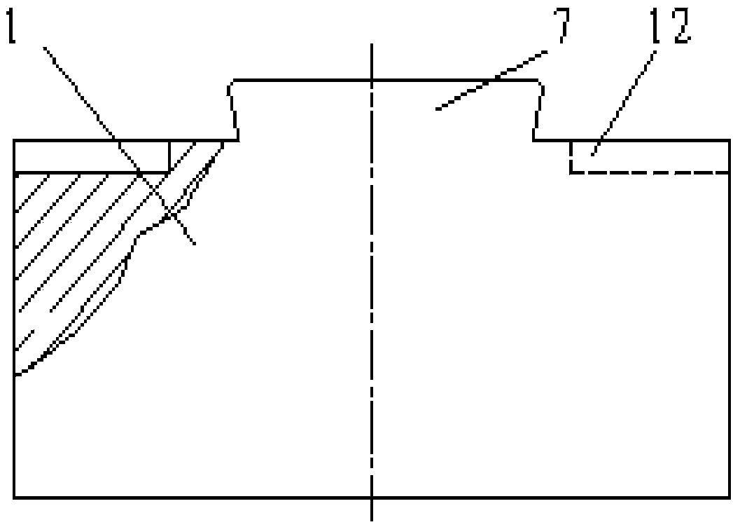
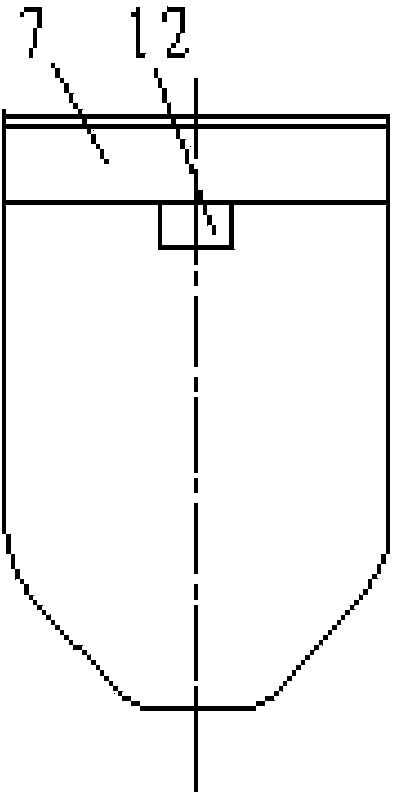
[0022] The inclined plane anvil of the present invention is made up of upper anvil part and lower anvil part, and upper anvil part is made of upper anvil and upper anvil seat, and lower anvil part is made of lower anvil 3 and lower anvil seat 4, and the bottom, upper part shape of upper and lower anvil Consistent with the shape of the conical surface of the connecting rod (see figure 2 , 4 ).

[0023] refer to figure 1 , 2 , 5, the upper anvil 1 of the upper anvil part ( figure 1 ) of the dovetail 7 snap into the dovetail groove 8 of the anvil 2, and the two are fixed as one by the tapered iron wedge 13 inserted, and the flat key 14 inserted into the anvil keyway 12 and the anvil keyway 11.

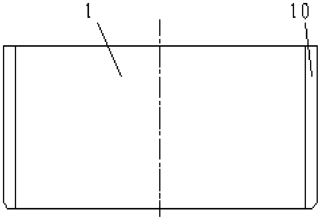
[0024] refer to image 3 , 4 , 6, the side protruding narrow side 10 of the lower anvil 3 of the lower anvil part is placed in the keyway 9 of the lower anvil.

[0025] T...


PUM


Abstract

The invention relates to an inclined plane anvil forging a connecting rod transition conical face and a transition conical face machining method thereof. An upper anvil portion is composed of an upper anvil and an upper anvil base, and a lower anvil portion is composed of a lower anvil and a lower anvil base. The lower portion shape of the upper anvil and the upper portion shape of the lower anvil are the same as the shape of a connecting rod machined conical face. A forked tail of the upper anvil of the upper anvil portion is clamped into a forked tail groove in the upper anvil base. The protruding narrow edge of the side face of the lower anvil of the lower anvil portion is arranged in a key groove in the lower anvil base. During machining, the upper anvil base is connected to a pressing machine connecting plate, the lower anvil and the lower anvil base are placed on a pressing machine walking table, a pressing machine is operated, a jaw of a blank operating machine clamps a blank, the blank is rotated, the lower plane of the upper anvil and the upper plane of the lower anvil form a connecting rod middle rod portion and a transition inclined plane, finishing is carried out by an upper flat anvil and a lower flat anvil, log marking and coining are carried out in sequence, and therefore the connecting rod middle transition conical face is formed. A connecting rod forged by the inclined plane anvil is regular in outline, simple in production procedures, high in material utilization rate, good in metal streamline performance, short in machining period and low in production cost. By means of the inclined plane anvil, connecting rods of marine diesel engines of the model number being 50 or larger than 50 can be produced.

Description

technical field [0001] The invention relates to a slope anvil for forging a transition cone surface of a connecting rod and a method for processing the transition cone surface with it. Background technique [0002] As an important part of a large marine diesel engine, the connecting rod has special working conditions and complex forces. It must not only have good mechanical properties, but also ensure a certain shape to meet the needs of special working conditions. [0003] At present, there is a conical surface in the middle of domestic marine connecting rods. The main production method is to use upper and lower flat anvils, free forging, and use traditional flat anvils to forge larger model connecting rods (50 machines and above models), whether forging or later machining. There are many deficiencies: First, in the forging process, because the flat anvil forging is difficult to forge the middle conical surface, the conical transition area between the two ends of the connec...

Claims


Application Information

Patent Timeline
IPC IPC(8): B21J13/06B21J5/00
CPCB21J13/06B21J5/00
Inventor 陈国红刘长安张承峰张广森廉荣光于海娟刘振新黄顺林肖海生陈飞李爽刘秀环林晨
Owner 武汉重工铸锻有限责任公司
Why Eureka
Try Eureka