Knife device and tool holder for such a tool device

A tool and tool holder technology, applied to the accessories of tool holders, milling cutters, manufacturing tools, etc., to achieve the effect of avoiding freezing

Active Publication Date: 2018-11-16
FRANZ HAIMER MASCHINENBAU KG
View PDF8 Cites 0 Cited by
  • Summary
  • Abstract
  • Description
  • Claims
  • Application Information

AI Technical Summary

Problems solved by technology

Toolholders must therefore be designed specifically for this cooling scheme

Method used


Image

  • Knife device and tool holder for such a tool device
  • Knife device and tool holder for such a tool device
  • Knife device and tool holder for such a tool device

Examples


Embodiment Construction

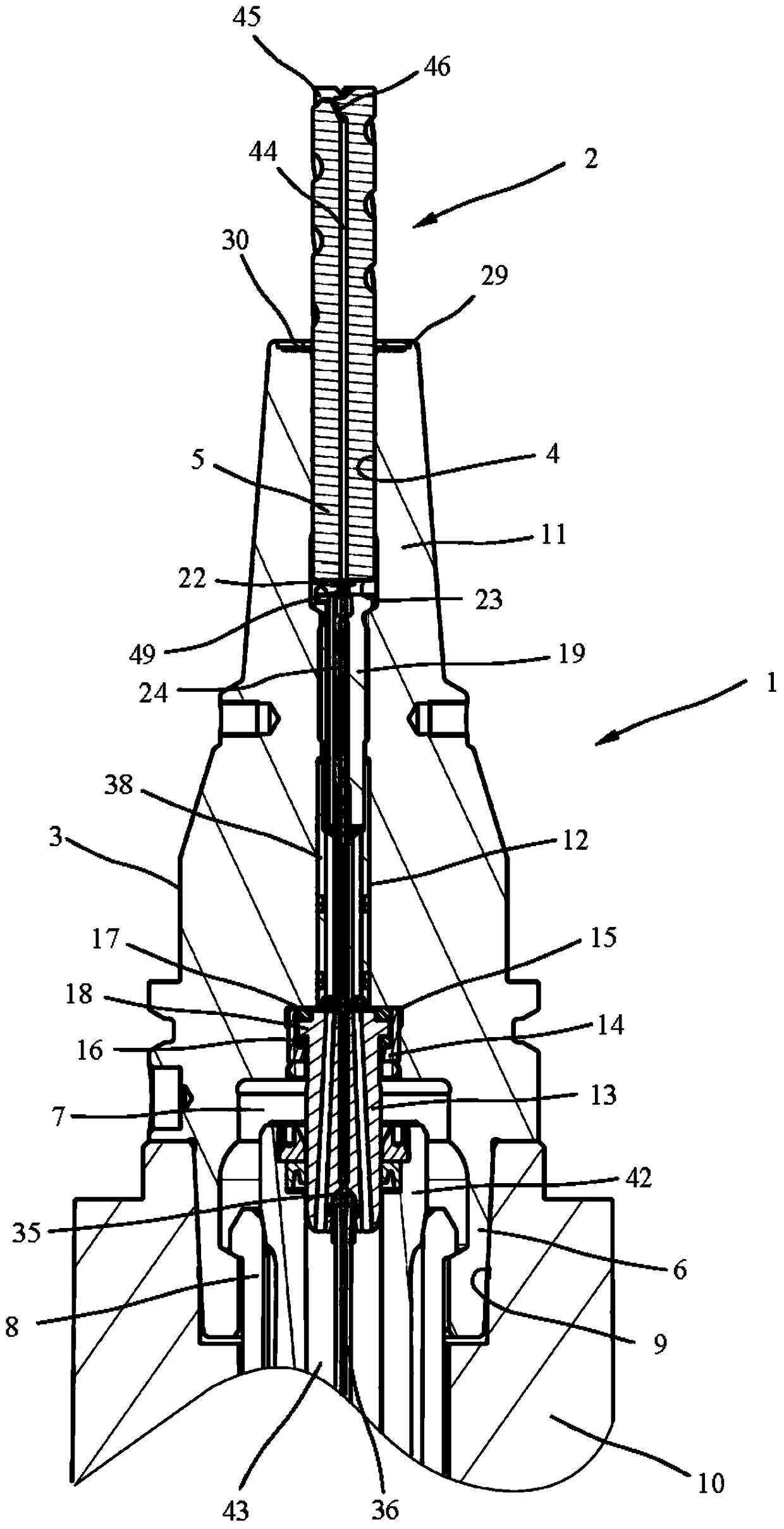
[0027] exist figure 1 An exemplary embodiment of a tool arrangement with a tool holder 1 and a tool 2 is shown in . Here, the tool holder 1, designed for example as an HSK (hollow taper shank, Hohlschaftkegel) tool holder, comprises a rotationally symmetrical tool holder body 3 that can rotate about a central axis, and which has, for example, a design on the tool-side end. A receiving hole 4 for a tool holder 5 of a tool 2 for a drill, milling cutter or the like, and on the end on the machine tool side comprises a clamping cone 6 which has a cavity 7 which Clamping part 8 for engaging the pliers. The tool holder 1 is mounted via a clamping cone 6 into a corresponding cone receptacle 9 of a machine tool spindle 10 and clamped via a pliers-shaped clamping part 8 of a clamping device integrated in the machine tool spindle 10 .

[0028] In the illustrated embodiment, the tool holder 1 is designed as a retractable collet and comprises a front clamping region 11 in which a tool ho...


PUM


Abstract

The invention relates to a tool arrangement with a tool holder (1) and a tool (2), wherein at least one fluid channel (24) for supplying a fluid to the tool (2) is provided in the tool arrangement. In order to be able to improve the alternate fluid delivery to the tool, the fluid channel (24) has at least one throttle position (49) for maintaining the pressure inside the fluid channel (24) upstream of the throttle position (49), the throttle The flow position is suitable to keep the pressure of the fluid high enough so that too much premature vaporization of the fluid does not occur.

Description

technical field [0001] The invention relates to a tool arrangement and a tool holder / holder for such a tool arrangement. Background technique [0002] Modern machine tools often have the possibility to deliver coolant internally. These possibilities generally include coolant delivery, by which coolant can be delivered to the tool through central coolant passages in the spindle of the machine tool and in the tool holder. [0003] A tool holder of this type is known from DE 10 2005 013 483 A1, in which fluid feed structures are provided in the tool holder body for feeding cooling fluid and / or lubricating fluid to a tool mounted in a receiving opening of the tool body. In this known tool holder, the fluid is conveyed through a channel in a tubular transfer part arranged in the tool holder body, through a channel in a stop sleeve arranged in the tool holder body and through a channel between the transfer part and the stop. The connecting pipe between the blocking sleeves is fo...

Claims


Application Information

Patent Timeline
Patent Type & Authority Patents(China)
IPC IPC(8): B23Q11/10B23B51/06B23C5/28
CPCB23B51/06B23C5/28B23Q11/1023B23B2231/24B23B31/0261Y10T409/304032Y10T279/17111B23Q11/1061
Inventor F·海莫
Owner FRANZ HAIMER MASCHINENBAU KG
Why Eureka
Try Eureka