Pouring device and construction method of grouted wall

A construction method and wall technology, applied in the processing of building materials, construction, building construction, etc., to achieve the effect of improving quality standards and improving technology

Inactive Publication Date: 2015-02-25
烟台驰龙建筑节能科技有限公司
View PDF10 Cites 8 Cited by
  • Summary
  • Abstract
  • Description
  • Claims
  • Application Information

AI Technical Summary

Problems solved by technology

The slurry using this pouring method is often affected by gravity in the process of falling downwards, and some air bubbles will be impacted, which often easily causes the separation, precipitation, collapse, delamination, hollowing, uneven density and other problems of the slurry, which is serious. It affects the quality index of the entire wall, resulting in the substandard design requirements of the entire wall
Over the years, grouted cast-in-place lightweight walls have not been widely used because the cast-in-place technology cannot meet the current standards

Method used


Image

  • Pouring device and construction method of grouted wall
  • Pouring device and construction method of grouted wall

Examples


Embodiment 1

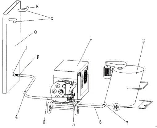
[0028] A reference to pouring equipment for a grouted wall in this embodiment figure 1 , including a cavity wall Q and a pumping machine 1 for pouring slurry into the cavity wall Q, the lower middle part of the cavity wall Q has a pouring hole J, and the upper part has an air guide hole K; The pumping machine 1 is connected to the pouring hole J through the slurry delivery pipe 4 and the valve body F. One end of the valve body F is connected to the pouring hole J of the cavity wall Q, and the other end is connected to the slurry delivery hole J. The pipe 4 is connected; the prepared slurry is transported by the pump 1 to the valve body F connected to the bottom of the cavity wall Q through the slurry delivery pipe 4, and the slurry is discharged to the valve body F through the valve body F. Inside the cavity wall Q; the air guide hole K above the cavity wall Q is connected with an air guide tube G; the pump 1 is also connected to a mixer 2, and the mixer 2 passes through the ...


PUM


Abstract

The invention relates to a pouring device and construction method of a grouted wall, and belongs to the technical field of grouted wall pouring. The pouring device of the grouted wall comprises a hollow wall and a pumping machine used for pouring grouting materials into the hollow wall, and is characterized in that a pouring hole is formed in the middle of the lower portion of the hollow wall, a gas vent is formed in the upper portion of the hollow wall, the pumping machine is connected to the pouring hole through a grouting material conveying pipe and a valve, one end of the valve is connected with the pouring hole of the hollow wall, and the other end of the valve is connected with the grouting material conveying pipe. The problem that the grouting materials disperse or settle or collapse or become layered or generate empty drums or become nonuniform in density in the falling process will not occur, and therefore the quality standard of the light poured-in-place wall is effectively improved.

Description

[0001] technical field [0002] The invention relates to pouring equipment and a construction method for grouting walls, and belongs to the technical field of grouting wall pouring. [0003] Background technique [0004] The current pouring method for light-weight cast-in-place thermal insulation and sound insulation walls is to pour from the top to the bottom through pouring holes or punching holes on the upper part of the wall, which is also called "upper pouring method". The upper part is poured from top to bottom, and the fluidity and sag of the slurry are used to fill the inside of the wall from bottom to top, and the wall is formed after solidification. The slurry using this pouring method is often affected by gravity in the process of falling downwards, and some air bubbles will be impacted, which often easily causes the separation, precipitation, collapse, delamination, hollowing, uneven density and other problems of the slurry, which is serious. It affects the qu...

Claims


Application Information

Patent Timeline
Patent Type & Authority Applications(China)
IPC IPC(8): E04G21/02E04G21/04
Inventor 牟衍龙牟世友冯明清张鋆刘丽君
Owner 烟台驰龙建筑节能科技有限公司
Why Eureka
Try Eureka