
Self-balancing type static balance valve

A statically balanced and self-balancing technology, applied in the direction of lift valves, valve devices, engine components, etc., can solve the problems of system pressure influence, loss of valve operability, stability and beauty, transportation, etc.

Active Publication Date: 2015-02-25
WATTS VALVE NINGBO
View PDF7 Cites 1 Cited by
  • Summary
  • Abstract
  • Description
  • Claims
  • Application Information

AI Technical Summary

Problems solved by technology

Therefore, in order to reduce the torque, the hand wheel of the traditional static balance valve will be enlarged according to the geometric progression of the caliber, but it is very powerless for the large-diameter static balance valve, and it is affected by the system pressure, and the loss of the valve At the expense of operability, stability, aesthetics, transportation, etc.

Method used


Image

  • Self-balancing type static balance valve
  • Self-balancing type static balance valve
  • Self-balancing type static balance valve

Examples


Embodiment Construction

[0022] In order to make the purpose, technical solutions and advantages of the embodiments of the present invention clearer, the technical solutions in the embodiments of the present invention will be clearly and completely described below in conjunction with the drawings in the embodiments of the present invention. Obviously, the described embodiments It is a part of embodiments of the present invention, but not all embodiments. Based on the embodiments of the present invention, all other embodiments obtained by persons of ordinary skill in the art without making creative efforts belong to the protection scope of the present invention.

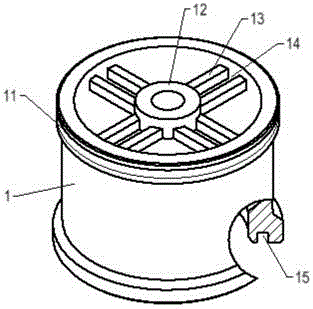
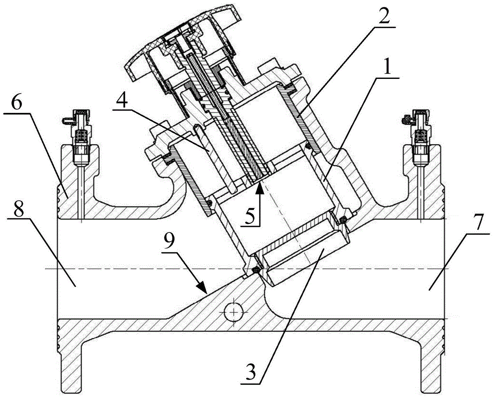
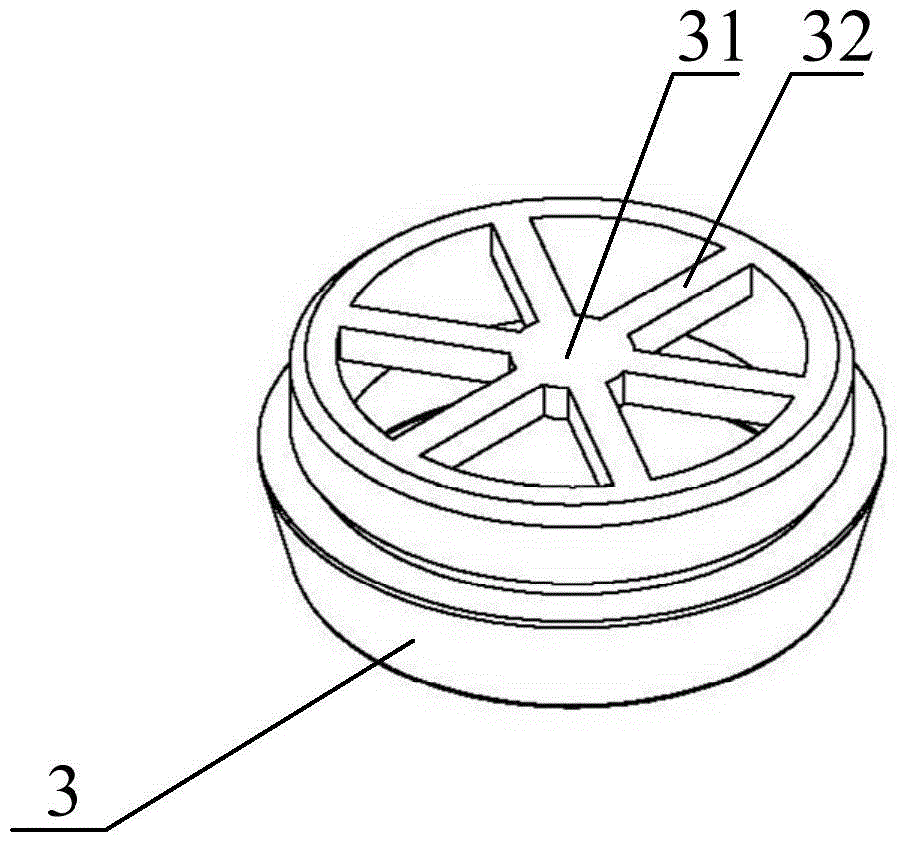
[0023] Please refer to Figure 1-Figure 3 , figure 1 Structural schematic diagram of the self-balancing static balancing valve provided for the embodiment of the present invention; figure 2 Schematic diagram of the structure of the disc sleeve provided by the embodiment of the present invention; image 3 Schematic diagram of the structure...


PUM


Abstract

The invention discloses a self-balancing type static balance valve. The self-balancing type static balance valve comprises a valve body, a valve rod, an inner layer sleeve, a sealing device, a valve clack sleeve and a valve clack, wherein the inner layer sleeve is fixed inside the valve body, the valve clack sleeve is connected with the inner layer sleeve in a motive seal mode, the valve clack is fixed at the bottom of the valve clack sleeve, the sealing device is arranged between the valve clack and the valve clack sleeve, a cavity inside the valve clack sleeve and a cavity inside the inner layer sleeve form an immediate hole cavity, and the inlet of the valve body is communicated with the immediate hole cavity. Whether the valve is in an opened or a closed state, the valve clack sleeve and the valve clack sleeve driven by an entire hand wheel mechanism are balanced in stress, therefore, torque needed for operating the valve is unrelated to system pressure or opening or closing of the valve, and the valve can be freely operated just by overcoming small frictional force. The self-balancing type static balance valve solves the problems that an existing balance valve is poor in operability and operation is difficult due to overlarge torque of a hand wheel.

Description

technical field [0001] The invention relates to the technical field of valves, in particular to a self-balancing static balancing valve. Background technique [0002] Static balance valve is also called balance valve, manual balance valve, digital lock balance valve, two-position regulating valve, etc. It changes the flow resistance flowing through the valve by changing the gap between the valve core and the valve seat. In order to achieve the purpose of regulating the flow, the object of action is the resistance of the system. [0003] Because the object of the static balance valve is fluid resistance, the parts in contact with the fluid will be affected by the system pressure. In the traditional static balance valve, because the middle hole is connected with the water outlet, the system pressure directly acts on the valve disc, and the valve disc is directly subjected to force N=PS (P is the system pressure, S is the pressure area of ​​the valve disc), and The torque M r...

Claims


Application Information

Patent Timeline
IPC IPC(8): F16K1/00F16K1/32F16K1/36F16K1/48
CPCF16K1/00F16K1/32F16K1/36F16K1/48
Inventor 吴强
Owner WATTS VALVE NINGBO
Learn More