Direct type backlight module and liquid crystal display

A backlight module, direct type technology, applied in the semiconductor devices, instruments, optics and other directions of light-emitting elements, can solve the problems of light loss, reduce light efficiency, increase the weight and cost of the backlight module, reduce the thickness and improve the mixing ratio. Optical distance, the effect of avoiding the phenomenon of bad optical taste

Inactive Publication Date: 2015-02-25
SOUTH CHINA UNIV OF TECH
View PDF4 Cites 13 Cited by
  • Summary
  • Abstract
  • Description
  • Claims
  • Application Information

AI Technical Summary

Problems solved by technology

Although this structure can achieve short-distance light mixing, after adding optical lenses, not only the weight and cost of the backlight module increase, but also the installation of the lens belongs to the secondary optical system, which will inevitably lead to loss of light and reduce the efficiency of light

Method used


Image

  • Direct type backlight module and liquid crystal display
  • Direct type backlight module and liquid crystal display
  • Direct type backlight module and liquid crystal display

Examples


Embodiment 1

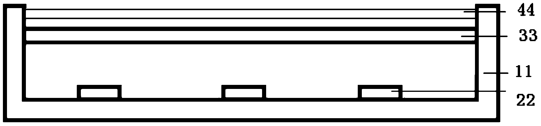
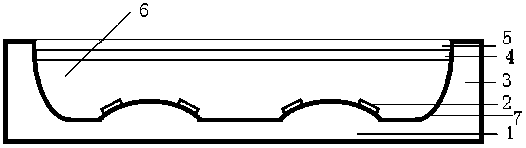
[0028] Such as figure 2 As shown, this embodiment discloses a direct type backlight module, including a backplane, a backlight 2, a diffusion plate 4 and an optical film layer 5, the backplane includes a bottom plate 1 and a side plate 3 connected to the bottom plate, and the side plate 3 and the bottom plate 1 to form a backlight cavity 4; the diffusion plate 3 is arranged on the side plate, and the optical film layer 5 is arranged on the top of the diffusion plate 4; the backlight source 2 is arranged on the bottom plate of the backplane and accommodated in the backlight cavity 6; The bottom plate 1 is a free-form surface, and the radian of the free-form surface of the bottom plate is adjusted according to the light mixing distance of the backlight; when the light mixing distance of the backlight is relatively short, the radian of the free-form surface should be appropriately increased, so that the light emitted by the backlight can obtain The longer optical path enables th...

Embodiment 2

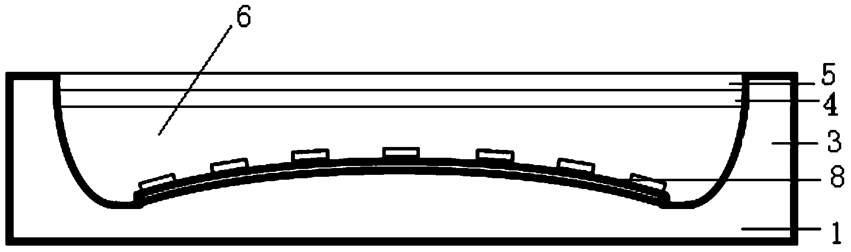
[0036] This embodiment discloses a direct type backlight module. The difference between this embodiment and Embodiment 1 is that, as image 3 As shown, the free-form bottom plate in this embodiment is composed of a circular arc surface, that is, the free-form surface on the free-form bottom plate is a continuous arc, and one or more backlight sources are arranged on the free-form surface. The backlight arranged on the free-form surface bottom plate is LED Bar light bar 8 light source, and a flexible circuit layer is arranged on the free-form surface of the bottom plate, and the LED Bar light bar 8 light source is bonded to the flexible circuit layer through silver paste, solder or other pasting materials. .

[0037] The bending degree of the LED Bar light bar 8 is adjusted according to the radian of the free-form surface bottom plate, thereby adjusting the light-emitting direction of the LED in the LED Bar light bar light source.

[0038]This embodiment also discloses a liqui...


PUM


Abstract

The invention discloses a direct type backlight module. The direct type backlight module comprises a backboard, a backlight source, a diffuser plate and an optical film layer. The backboard comprises a bottom board and side boards connected to the bottom board, and a backlight cavity is formed by the side boards and the bottom board. The diffuser plate is arranged on the side boards, and the optical film layer is arranged on the diffuser plate. The backlight source is arranged on the bottom board of the backboard and contained in the backlight cavity. The bottom board of the backboard is a free curved face, and the radian of the free curved face of the bottom board is adjusted according to the light mixing distance of the backlight source. The bottom board of the backboard of the direct type backlight module is the free curved face, the light-emitting pointing direction of the backlight source is adjusted through the radian of the curved face of the bottom board, and it is avoided that the pointing direction of the maximum light intensity of the backlight source is directly perpendicular to the backlight module, bad optical goods phenomena such as the firefly effect are avoided, meanwhile, the light mixing distance is increased, the needed thickness of the backlight cavity is reduced, and the backlight module can be lighter and thinner.

Description

technical field [0001] The invention relates to a backlight source structure, in particular to a direct type backlight module and a liquid crystal display. Background technique [0002] In recent years, flat panel display technology has developed by leaps and bounds, and the demand for thin, light and large-size liquid crystal displays is increasing. Since liquid crystal is a material that cannot emit light, a liquid crystal display needs to add a backlight under the liquid crystal to present images. According to the position of the light source, the backlight can generally be divided into side-lit type and direct-lit type. For the side-light type, the light source is installed on the side of the liquid crystal panel. The light source enters the light guide plate from the side, and is converted into a surface light source by the light guide plate and then supplied to the liquid crystal panel. It needs to mix light and color through the light guide plate. The luminous unifo...

Claims


Application Information

Patent Timeline
Patent Type & Authority Applications(China)
IPC IPC(8): F21S8/00F21V7/22G02F1/13357F21Y101/02
CPCF21S8/00F21V7/22F21Y2105/10F21Y2115/10G02F1/133603
Inventor 文尚胜陈颖聪
Owner SOUTH CHINA UNIV OF TECH
Why Eureka
Try Eureka