Vehicular lamp

A technology for lamps and vehicles, which is applied in the direction of headlights, road vehicles, vehicle parts, etc., can solve the problem of light distribution pattern deviation, and achieve the effect of suppressing position deviation

Active Publication Date: 2015-02-25
KOITO MFG CO LTD
View PDF8 Cites 6 Cited by
  • Summary
  • Abstract
  • Description
  • Claims
  • Application Information

AI Technical Summary

Problems solved by technology

[0005] However, when the mounting position of the LED deviates from the specified position, the positional relationship between the LED and the reflector changes, so the light does not exit along the specified optical axis direction, and there is a possibility that the light distribution pattern deviates from the specified position. possibility

Method used


Image

  • Vehicular lamp
  • Vehicular lamp
  • Vehicular lamp

Examples


Embodiment Construction

[0022] Hereinafter, a vehicle lamp according to an embodiment of the present invention will be described in detail with reference to the drawings. It should be noted that when terms such as "up", "down", "front", "rear", "left", "right", "inside" and "outside" are used in this manual, they mean that the vehicle lamp is installed on the vehicle. The orientation of the posture at the time.

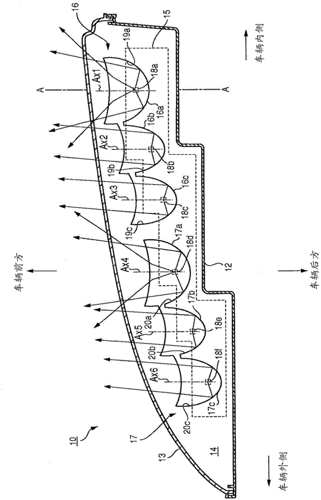
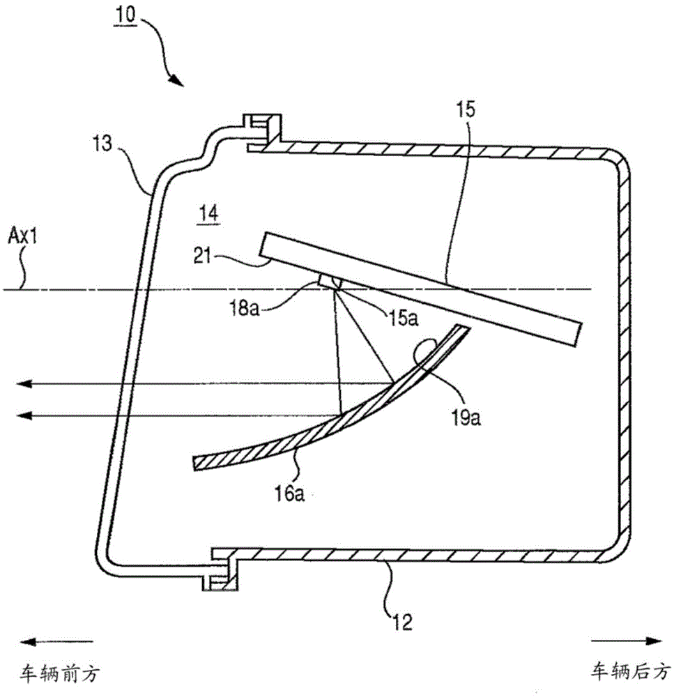
[0023] figure 1 It is a schematic horizontal cross-sectional view showing the vehicle lamp 10 according to the embodiment of the present invention. in addition, figure 2 yes means figure 1 A-A sectional view of the illustrated vehicle lamp 10 . figure 1 The vehicle lamp 10 shown is a headlamp arranged one on each side of the front of the vehicle. Since the structure is substantially the same on the left and right, the structure of the vehicle lamp arranged on the left side of the vehicle will be representatively described.

[0024] Such as figure 1 and figure 2 As shown, the vehicle...


PUM


Abstract

A vehicular lamp has a light source attachment flat surface having a plurality of light source attachment portions, a plurality of light sources attached to the plurality of light source attachment portions, and a plurality of parabolic reflectors. Each of the plurality of parabolic reflectors reflect light from a corresponding one of the light sources in a predetermined optical axis direction. The light source attachment flat surface is tilted with respect to an optical axis of the reflector so as to be higher on a front side of the lamp than on a rear side of the lamp.

Description

technical field [0001] The present invention relates to a vehicular lamp, and particularly relates to a vehicular lamp using a light-emitting element such as an LED and a parabolic reflector. Background technique [0002] Conventionally, a vehicular lamp is known that includes a plurality of LEDs and a plurality of reflectors that reflect light from the LEDs (for example, refer to Patent Document 1). [0003] Patent Document 1: Japanese Unexamined Patent Publication No. 2011-81975 [0004] Generally, when a vehicle lamp is configured using LEDs and a parabolic reflector, a plane on which LEDs are mounted (hereinafter referred to as "light source mounting plane") is provided parallel to the optical axis of the reflector. When the LED and the reflector are in a predetermined positional relationship, light is emitted in the direction of the optical axis of the predetermined reflector, and a light distribution pattern is formed at a predetermined position in front of the vehicl...

Claims


Application Information

Patent Timeline
Patent Type & Authority Applications(China)
IPC IPC(8): F21S8/10F21V7/06F21V23/00F21W101/02F21Y101/02F21W107/10
CPCF21S48/1225F21Y2101/02F21K9/50F21S41/141F21S41/32F21W2102/00F21W2107/10F21S41/147F21S41/148F21S41/151F21S41/19F21S41/336F21S43/14F21S43/19F21S43/31F21S41/285
Inventor 山本逸平
Owner KOITO MFG CO LTD
Why Eureka
Try Eureka