Gas-liquid separating type multiphase flowmeter

A multi-phase flowmeter and gas-liquid separation technology, which is applied in the direction of liquid/fluid solid measurement, volume flow measurement device, measurement device, etc., can solve the problems of discouraging the use of radiation, poor measurement accuracy of water content, and complex structure, etc., to achieve Easy to use and operate, high measurement accuracy, and the effect of measuring environmental friendliness

Inactive Publication Date: 2015-02-25
QINGDAO UNIV OF SCI & TECH
View PDF5 Cites 9 Cited by
  • Summary
  • Abstract
  • Description
  • Claims
  • Application Information

AI Technical Summary

Problems solved by technology

The traditional metering method is to send the crude oil extracted from the oil well into the three-phase separator, through which the crude oil is divided into three phases of oil, water and gas, and then the three fluids are measured separately through the flowmeter installed at the outlet of each phase of the separator; but these The traditional gas-liquid separator is complex in structure, large in size, and high in cost, which adds great difficulty to design and manufacture, and reduces the practicability of multiphase flowmeters; the combined measurement method of oil-water-gas multiphase flow can save space , funds and can continuously measure the production of each oil well in real time, and simplify the process
At present, the oil reservoir dynamic analysis and research in the oil well production measurement room is one of the indispensable procedures in the oilfield production management process. The existing research work on oil, gas and water multiphase flowm

Method used


Image

  • Gas-liquid separating type multiphase flowmeter

Examples


Embodiment

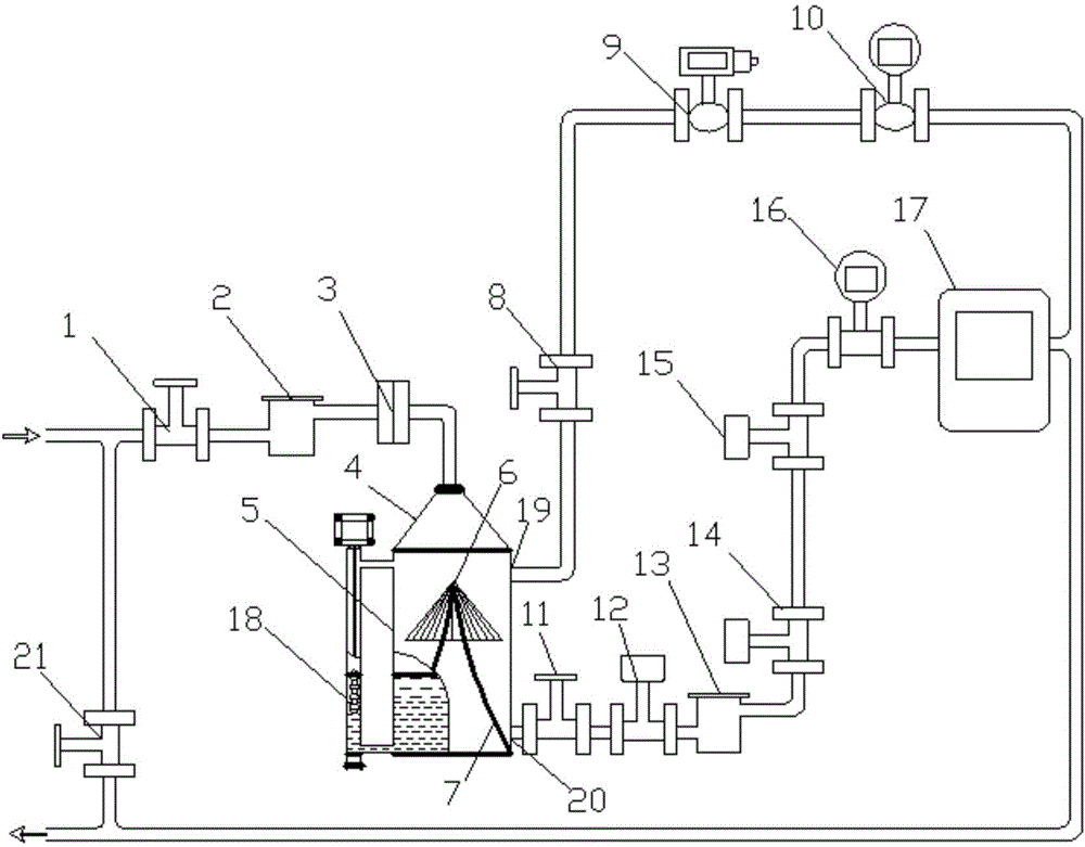
[0010] The main structure of the multiphase flowmeter involved in this embodiment includes: a first valve 1, a first heater 2, a flange 3, an oil-gas-water three-phase separator upper cover 4, an oil-gas-water three-phase separator 5, and a swirl plate tower 6. Swirl plate tower support 7, second valve 8, pressure transmitter 9, gas flow meter 10, third valve 11, first temperature sensor 12, second heater 13, second temperature sensor 14, third Temperature sensor 15, liquid flow meter 16, electronic display instrument 17, crude oil level gauge 18, gas phase outlet 19, liquid phase outlet 20 and fourth valve 21, all components are assembled and connected by pipelines to form an integrated gas-liquid separation type multi-phase flowmeter; the upper end of the oil-gas-water three-phase separator 5 with a swirling plate cylindrical structure is connected with the gas measuring pipeline through the flange 3, the first heater 2, the first valve 1, and the oil-gas-water three-phase se...


PUM


Abstract

The invention belongs to the technical field of metering equipment, and relates to a gas-liquid separating type multiphase flowmeter. The gas-liquid separating type multiphase flowmeter is assembled through a pipeline to form an integrated structure. The upper end is communicated with a gas measuring pipe through a flange, a first heater and a first valve, and the lower end is connected with an oil-water two-phase measuring pipe through a first temperature sensor and a second heater. A gas phase outlet is formed in the top of the side wall, and a liquid phase outlet is formed in the bottom of the side wall. An inner rotational flow plate tower support is fixed to the bottom of the inner wall, and a rotational flow plate tower is placed on the top of the rotational flow plate tower support. When the gas-liquid separating type multiphase flowmeter is used, oil-gas-water mixed liquid is processed through a gas-liquid two-phase separator, the exhausted gas is mixed with the oil-water mixed liquid which is heated by the heaters and measured by the temperature sensor and a liquid flowmeter after being measured by a pressure transmitter and a gas flowmeter, and the mixed gas and oil-water mixed liquid enters a downstream pipeline to flow out. The main gas-liquid separating type multiphase flowmeter is simple in structure, reliable in design principle, convenient to use and operate, high in metering accuracy, friendly in measuring environment and high in automation degree.

Description

Technical field: [0001] The invention belongs to the technical field of metering equipment, and relates to a separate metering device for oil-gas-water multiphase flow. Background technique: [0002] The oil-gas-water multiphase flowmeter is an instrument for measuring the oil-gas-water three-phase flow when the crude oil exploited in the oilfield is transported to the pipeline. The online measurement of the oil-water-gas multiphase fluid has a particularly large economic value. The traditional metering method is to send the crude oil extracted from the oil well into the three-phase separator, through which the crude oil is divided into three phases of oil, water and gas, and then the three fluids are measured separately through the flowmeter installed at the outlet of each phase of the separator; but these The traditional gas-liquid separator is complex in structure, large in size, and high in cost, which adds great difficulty to design and manufacture, and reduces the pra...

Claims


Application Information

Patent Timeline
IPC IPC(8): G01F7/00
Inventor 王展旭王智良王旌舟高振明
Owner QINGDAO UNIV OF SCI & TECH
Why Eureka
Try Eureka