Transformer

A transformer and lamination technology, applied in the field of transformers, can solve problems such as poor contact, power reduction, and reactance reduction, and achieve the effects of avoiding power reduction or coil heating and burning, avoiding varnish damage, and avoiding power reduction

Inactive Publication Date: 2015-02-25
MIANYANG RONGFU ELECTRONICS TECH
View PDF5 Cites 0 Cited by
  • Summary
  • Abstract
  • Description
  • Claims
  • Application Information

AI Technical Summary

Problems solved by technology

However, this structure will have problems during use, that is, it is necessary to ensure that the positions of the I stack and the E stack are fixed. Since the I stack and the E stack are in contact, it is prone to problems, that is, the I stack and the E stack are in contact with each other. The position of the laminations is prone to shift, which makes the contact between the two poor. Similar to the reduction of the iron core, the reactance is reduced, and the power is also reduced. In severe cases, the coil may even heat up or burn out.

Method used


Image

  • Transformer
  • Transformer
  • Transformer

Examples


Embodiment 1

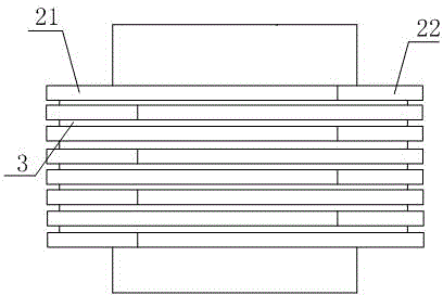
[0020] Such as figure 1 , figure 2 and image 3 The shown transformer includes a core element, and the core element includes a plurality of flat laminations stacked adjacent to each other so as to be in parallel, and the laminations include E laminations 21 and E laminations 21 constitutes the second laminated sheet 22 in the shape of a "day", the contact part of the E laminated sheet 21 and the second laminated sheet 22 is provided with teeth that engage with each other, and an anti-slip layer 3 is provided between the laminated sheets. The antiskid layer 3 is provided with holes. The stitching method between the E lamination and the second lamination is the same as that of the prior art, and has the same thickness. The center arm of the E-stack is located in the center of the spool 1.

Embodiment 2

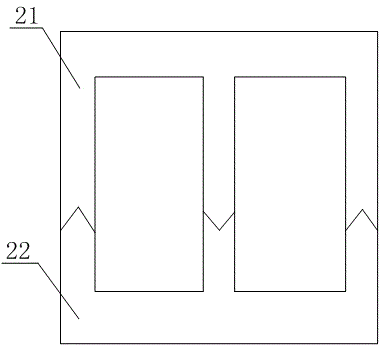
[0022] Such as figure 1 and figure 2 In the shown transformer, this embodiment is based on the above-mentioned embodiment, and an implementation mode is preferred for the second lamination, that is, the cross-section of the second lamination 22 is "E"-shaped. The section of the second lamination 22 is "E" shape, which increases the contact area of ​​the second lamination 22 with the anti-skid layer, so that the second lamination 22 is not easy to be pulled off, which is a preferred embodiment.

Embodiment 3

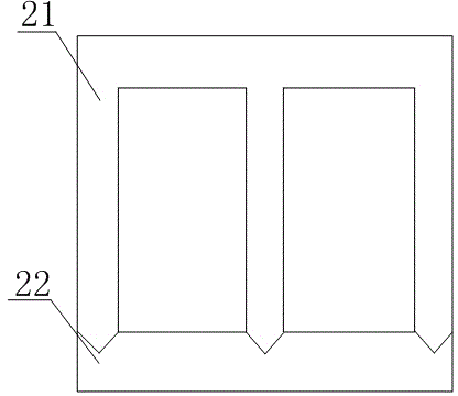
[0024] Such as figure 1 and image 3 In the shown transformer, this embodiment is based on the above-mentioned embodiment, and an implementation mode is preferred for the second lamination, and the cross-section of the second lamination 22 is "I" shape.


PUM


Abstract

The invention discloses a transformer which comprises an iron core element. The iron core element comprises a plurality of parallel flat stacked pieces which are adjacently stacked. The stacked pieces include E-shaped stacked pieces and second stacked pieces, wherein the E stacked pieces and the second stacked pieces form 'B' shapes, the contact parts of the E stacked pieces and the second stacked pieces are provided with meshed teeth, and antiskid layers provided with holes are disposed among the stacked pieces. The transformer has the advantages that the iron core element is stable in structure and less prone to stacked piece displacement, and power reduction and coil heating and burning during use are avoided.

Description

[0001] technical field [0002] The invention relates to a transformer. Background technique [0003] The transformer uses the principle of mutual inductance to change the AC voltage and consists of a primary coil, a secondary coil and an iron core. The structure of the existing transformer core includes a plurality of laminations, and the laminations include lamination elements with sections "I" and "E", and the I laminations and the E laminations form a "day"-shaped lamination. The center arm of the E-stack is located in the center of the spool 1. Since the laminations are stacked one by one, that is, after the I laminations of the first layer and the E laminations are butted, the laminations of the second layer are assembled on the core element in the opposite direction, that is, the upper and lower adjacent laminations of the I laminations are all E stack. However, this structure will have problems during use, that is, it is necessary to ensure that the positions of ...

Claims


Application Information

Patent Timeline
Patent Type & Authority Applications(China)
IPC IPC(8): H01F27/26H01F27/245
Inventor 林中金田仁模
Owner MIANYANG RONGFU ELECTRONICS TECH
Why Eureka
Try Eureka