PFC common mode inductor

A technology of common-mode inductors and coils, applied in the field of PFC common-mode inductors, can solve problems such as inconvenient replacement, and achieve the effects of easy replacement, easy selection, and easy operation

Inactive Publication Date: 2015-02-25
MIANYANG RONGFU ELECTRONICS TECH
View PDF7 Cites 4 Cited by
  • Summary
  • Abstract
  • Description
  • Claims
  • Application Information

AI Technical Summary

Problems solved by technology

[0005] The existing common mode inductor contains two coils. When in use, when there is a problem with any coil of the inductor, the entire inductor needs to be replaced. Since the inductor is fixed on the circuit board, the position of each component has been fixed. When replacing Very inconvenient, not only need to remove the inductance but also need to fix and connect the new inductance

Method used


Image

  • PFC common mode inductor

Examples


Embodiment 1

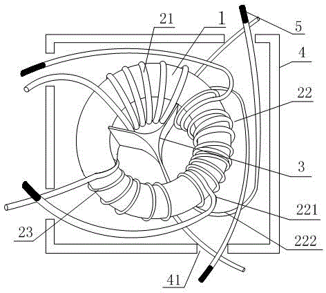
[0022] Such as figure 1 A PFC common mode inductor shown includes a casing 4, a magnetic core 1 inside the casing 4, and a coil wound on the magnetic core 1, the coil includes a first coil 21 and a third coil 23, and the The casing 4 is provided with lead wire holes 41, and the two ends of the first coil 21 and the third coil 23 are respectively located in different lead wire holes 41, and the coils also include the second coil 22, and the second coils 23 The coil 22 includes a first backup coil 221 with the same number of turns and the same winding direction as the third coil 23 and a second backup coil 222 with the same number of turns as the first coil 21 and the same winding direction. The two ends of 221 and the third coil 23 are located in the same lead hole 41, and the two ends of the second backup coil 222 and the first coil 21 are located in the same lead hole 41. Both ends of the first backup coil 221 and the second backup coil 222 are provided with a distinguishing...

Embodiment 2

[0025] Such as figure 1 The PFC common mode inductor shown in this embodiment is optimized on the basis of the above embodiments, and spacers 3 are provided between the first coil 21 , the second coil 22 and the third coil 23 .

[0026] The spacer 3 is in the shape of a "herringbone".

Embodiment 3

[0028] Such as figure 1 A PFC common mode inductor shown in this embodiment is refined on the basis of the above embodiments, that is, the distinguishing device 5 is a wire cap. It is simple and easy to use the wire cap to distinguish the spare coils, and the wire cap can be directly put on the coil head, and the operation is simple.


PUM


Abstract

The invention discloses a PFC common mode inductor which comprises a shell, a magnetic core located in the shell and a coil winding on the magnetic core. The coil includes a first coil and a third coil. Lead holes are formed in the shell. Two ends of the first coil and the third coil are respectively located in different lead holes. The coil further includes a second coil. The second coil includes a first standby coil and a second standby coil, wherein the turns and winding direction of the first standby coil are identical with the turns and the winding direction of the third coil, the turns and winding direction of the second standby coil are identical with the turns and winding direction of first coil, two ends of the first standby coil and the two ends of the third coil are located in the same lead holes, two ends of the second standby coil and the two ends of the first coil are located in the same lead holes, and distinguishing devices are disposed at two ends of the first standby coil and at two ends of the second standby coil. The PFC common mode inductor is easy to maintain and replace.

Description

[0001] Technical field [0002] The invention involves the field of co -modular inductance, and more specifically, it involves a PFC co -modular inductance. Background technique [0003] PFC is the power factor correctioner. It can increase the utilization rate of the municipal power when the communication is converted to DC, but it cannot reduce the power loss of the conversion process.PFC is divided into two types: active and passive, which is an important factor in measuring its level.PFC generally includes capacitors, common modulus inductors, switching tubes and control chips. [0004] The co -modular inductance has the effect of inhibiting the changes in current. The greater the less inductance, the more obvious the effect. This effect is called sensor resistance. The size of the sensor resistance is related to the operating frequency of the inductance and the size of its inductance. [0005] The existing co -mode inductance contains two coils. When used, when there is a pr...

Claims


Application Information

Patent Timeline
Patent Type & Authority Applications(China)
IPC IPC(8): H01F27/30
Inventor 林中金田仁模
Owner MIANYANG RONGFU ELECTRONICS TECH
Why Eureka
Try Eureka