Power transformer

A technology of power transformers and transformers, applied in the direction of transformers/inductor coils/windings/connections, etc., can solve problems such as inconvenient use, and achieve the effect of convenient winding and high safety factor

Inactive Publication Date: 2015-02-25
DONGGUAN JIZHISHENG ELECTRONICS SCI & TECH
View PDF4 Cites 0 Cited by
  • Summary
  • Abstract
  • Description
  • Claims
  • Application Information

AI Technical Summary

Problems solved by technology

[0004] For the transformer of th

Method used


Image

  • Power transformer

Examples


Embodiment 1

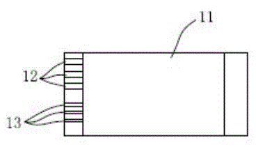
[0015] Embodiment 1, with reference to figure 1 ,See figure 1 , a power transformer of the present invention includes: a main body 11, an auxiliary winding tank 12, and an input winding wire. 12. The input winding slots 13 are arranged unevenly, the radial width of the auxiliary winding slots 12 is greater than the radial width of the input winding slots 13, and the distance between adjacent auxiliary winding slots 12 is greater than that of adjacent input winding slots 13 The adjacent auxiliary winding slots 12 are arranged more sparsely, the adjacent input winding slots 13 are arranged more densely, and the pins set in the auxiliary winding slots 12 and the pins set in the input winding slots 13 are uneven. Spacing arrangement.

[0016] Since the auxiliary winding slot body 12 and the input winding slot body 13 are arranged at uneven and uneven intervals, the winding is more convenient, the distance between the tail wire and the transformer core is larger, and the safety...


PUM


Abstract

The invention relates to the technical field of transformers, in particular to a power transformer. According to the technical scheme, the power transformer comprises a transformer body provided with auxiliary winding grooves and input winding grooves and is characterized in that the auxiliary winding grooves and the input winding grooves are arranged unevenly at unequal intervals. The power transformer has the advantages that since the auxiliary winding grooves and the input winding grooves are arranged unevenly in a manner of different densities, winding is facilitated, the distance between the tail wire and the magnetic core of the transformer body is increased, and the safety coefficient is larger.

Description

technical field [0001] The invention relates to the technical field of transformer machinery manufacturing, in particular to a power transformer. Background technique [0002] At present, the application of LED in daily lighting is becoming more and more popular. From outdoor lighting to indoor lighting, you can see the footprint of LED lighting products. LED has the characteristics of energy saving, environmental protection, long life, and easy control. Long life, power saving and other characteristics, become a relatively important member of indoor lighting applications. Switching power supply as an important component of LED fluorescent tube [0003] Components, the main use of isolated power supply. The isolated power supply means that the input terminal and the output terminal are isolated by a transformer, which can isolate the input and output, and has high safety. Due to the limited space in the lamp, the temperature inside the lamp will rise after working for a c...

Claims


Application Information

Patent Timeline
IPC IPC(8): H01F27/30
Inventor 钟远东蓝建文
Owner DONGGUAN JIZHISHENG ELECTRONICS SCI & TECH
Why Eureka
Try Eureka