Cutting device for motor coil production

A technology for cutting devices and coils, applied in the direction of electromechanical devices, manufacturing motor generators, electrical components, etc., can solve problems such as low production efficiency, accident-prone, and affecting device practicability, so as to improve product quality and ensure stable rotation performance and improve the practicality of the device

Active Publication Date: 2021-04-06
KUNGFU SCI TECH CO LTD
View PDF17 Cites 0 Cited by
  • Summary
  • Abstract
  • Description
  • Claims
  • Application Information

AI Technical Summary

Problems solved by technology

[0002] Motor (commonly known as "motor") refers to an electromagnetic device that realizes the conversion or transmission of electric energy according to the law of electromagnetic induction. After the wire is completed, the excess coil needs to be cut. At present, in the prior art, scissors are generally used to cut the coil after the motor stator is wound. The staff needs to hold the motor electronics in one hand and the scissors in the other hand To cut the coil, the cutting process is cumbersome, and the scissors are placed next to the device, which is prone to accidents. Therefore, there is an urgent need for a cutting device for the production of motor coils
[0003] After retrieval, the Chinese patent application number is CN201922079061.2, which discloses a cutting device for vibrating motor production, which aims at the high labor intensity and low production efficiency of existing workers, while the existing reaction

Method used


Image

  • Cutting device for motor coil production
  • Cutting device for motor coil production
  • Cutting device for motor coil production

Examples


Example Embodiment

[0029]The technical solutions of this patent will be described in further detail below in conjunction with specific embodiments.

[0030]The embodiments of this patent are described in detail below, and examples of the embodiments are illustrated in the drawings, wherein the same or similar reference numerals are indicated by the same or similar elements or elements having the same or similar functions. The following is exemplary, and is intended to explain this patent by referring to the embodiments described with reference to the accompanying drawings.

[0031]In the description of this patent, it is to be understood that the term "center", "upper", "lower", "front", "post", "left", "right", "vertical", "horizontal", The orientation relationship between "top", "bottom", "inside", "outside", etc. is based on the orientation or positional relationship shown in the drawings, is only for easy description of this patent and simplified description, not indication or implied The device or elem...


PUM


Abstract

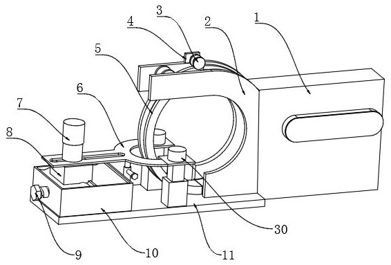
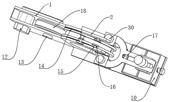
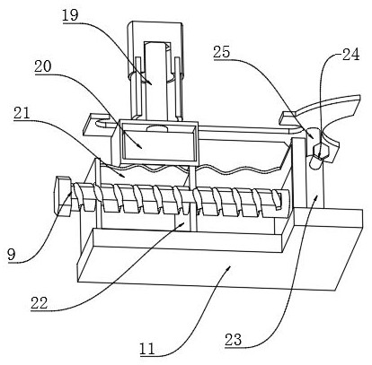
The invention discloses a cutting device for motor coil production and relates to the technical field of motor coil cutting. A problem that the cutting process is tedious during motor wire coil production is solved. Specifically, an outer wall of one side of a machine shell is fixedly connected with an arc-shaped baffle through screws; a winding ring is arranged on the inner wall of one side of the arc-shaped baffle; the outer wall of one side of the winding ring is connected with a connecting ring through a hinge; a magnet layer is arranged on the outer wall of one side of the winding ring; a square through groove is formed in the inner wall of the other side of the winding ring; a supporting spring is arranged on the inner wall of one side of the connecting ring; the outer wall of one side of the supporting spring is fixedly connected with an arc-shaped stop lever; the outer wall of one side of the connecting ring is slidably connected with a cutter. By arranging the square through groove, the square hole, the cutting rod, the cutting tool, the supporting spring and the arc-shaped stop lever, the cutting rod is pressed down, the arc surface of the arc-shaped stop lever is extruded by one side of the square hole to move downwards, so the cutting tool extends out of a cutting copper wire, and meanwhile the fixed circular ring relation between the winding ring and the connecting ring is relieved.

Description

technical field [0001] The invention relates to the technical field of motor coil winding, in particular to a cutting device for motor coil production. Background technique [0002] Motor (commonly known as "motor") refers to an electromagnetic device that realizes the conversion or transmission of electric energy according to the law of electromagnetic induction. After the wire is completed, the excess coil needs to be cut. At present, in the prior art, scissors are generally used to cut the coil after the motor stator is wound. The staff needs to hold the motor electronics in one hand and the scissors in the other hand To cut the coil, the cutting process is cumbersome, and the scissors are placed next to the device, which is prone to accidents. Therefore, there is an urgent need for a cutting device for the production of motor coils. [0003] After retrieval, the Chinese patent application number is CN201922079061.2, which discloses a cutting device for vibrating motor p...

Claims


Application Information

Patent Timeline
IPC IPC(8): H02K15/00H02K15/08B21F11/00
CPCB21F11/00H02K15/00H02K15/08
Inventor 龚爽
Owner KUNGFU SCI TECH CO LTD
Why Eureka
Try Eureka