

Display panel
A display panel and substrate technology, applied in the direction of instruments, electrical components, circuits, etc., can solve the problems of complex circuit design, different brightness attenuation range of light-emitting components, and affecting the color saturation of the display panel, etc.
- Summary
- Abstract
- Description
- Claims
- Application Information
AI Technical Summary
Problems solved by technology
Method used
Image

Examples
Embodiment Construction
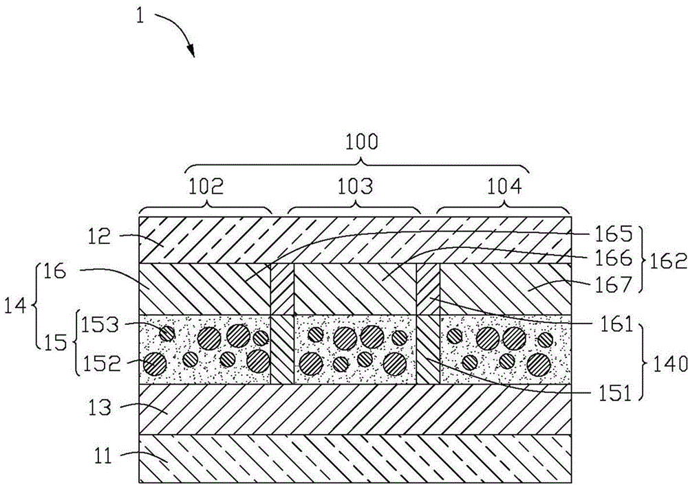
[0014] see figure 1 , which is a schematic diagram of the first embodiment of the display panel 1 of the present invention. In order to clearly illustrate the preferred embodiment of the present invention, the following diagram only shows one pixel area. The display panel 1 is used to display images in full color, and the display panel 1 may be a liquid crystal display panel or an organic electroluminescent display panel. In this embodiment, the display panel 1 is an organic electroluminescent display panel.
[0015] The display panel 1 includes a first substrate 11 and a second substrate 12 oppositely disposed. The display panel 1 defines a plurality of pixel areas 100 , and each pixel area 100 includes a first block 102 , a second block 103 and a third block 104 for emitting different color component lights. The first substrate 11 is provided with an organic electroluminescent element 13 for emitting monochromatic light. The organic electroluminescent element 13 is locate...
PUM
 Abstract
Description
Claims
Application Information