Decompression device

一种减压装置、蒸气压缩的技术,应用在阀装置、阀的吸收流体能量的装置、照明和加热设备等方向,达到抑制噪声产生的效果

Inactive Publication Date: 2015-02-25
DENSO CORP
View PDF10 Cites 0 Cited by
  • Summary
  • Abstract
  • Description
  • Claims
  • Application Information

AI Technical Summary

Problems solved by technology

[0004] In the decompression device of Patent Document 1, the pressure of the refrigerant depressurized and boiled by passing through the throttling passage of the thermal expansion valve is restored at the inlet of the nozzle part of the ejector, and boiling is generated in the refrigerant flowing into the nozzle part. Nucleation, thereby promoting the boiling of the refrigerant in the nozzle part to suppress the decline in nozzle efficiency

Method used


Image

  • Decompression device
  • Decompression device
  • Decompression device

Examples


no. 1 approach

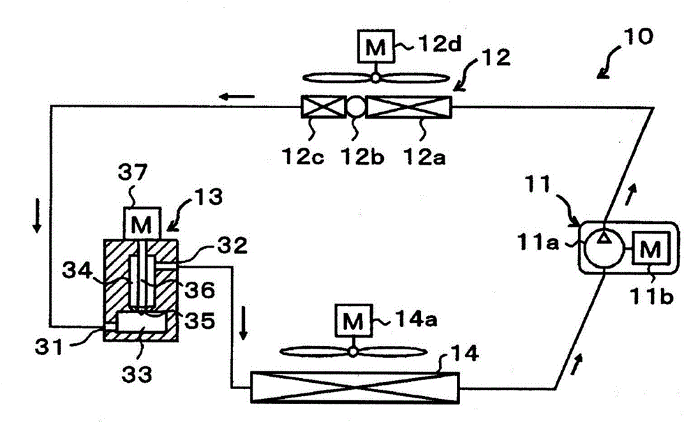
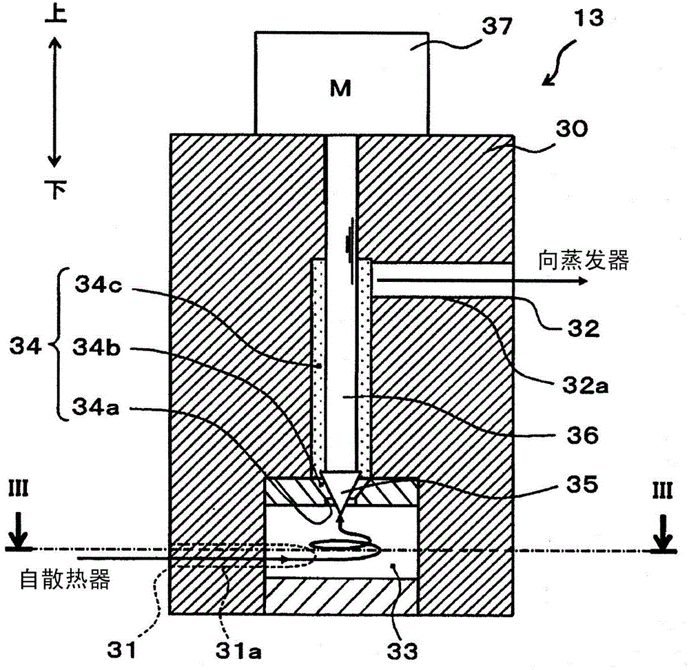
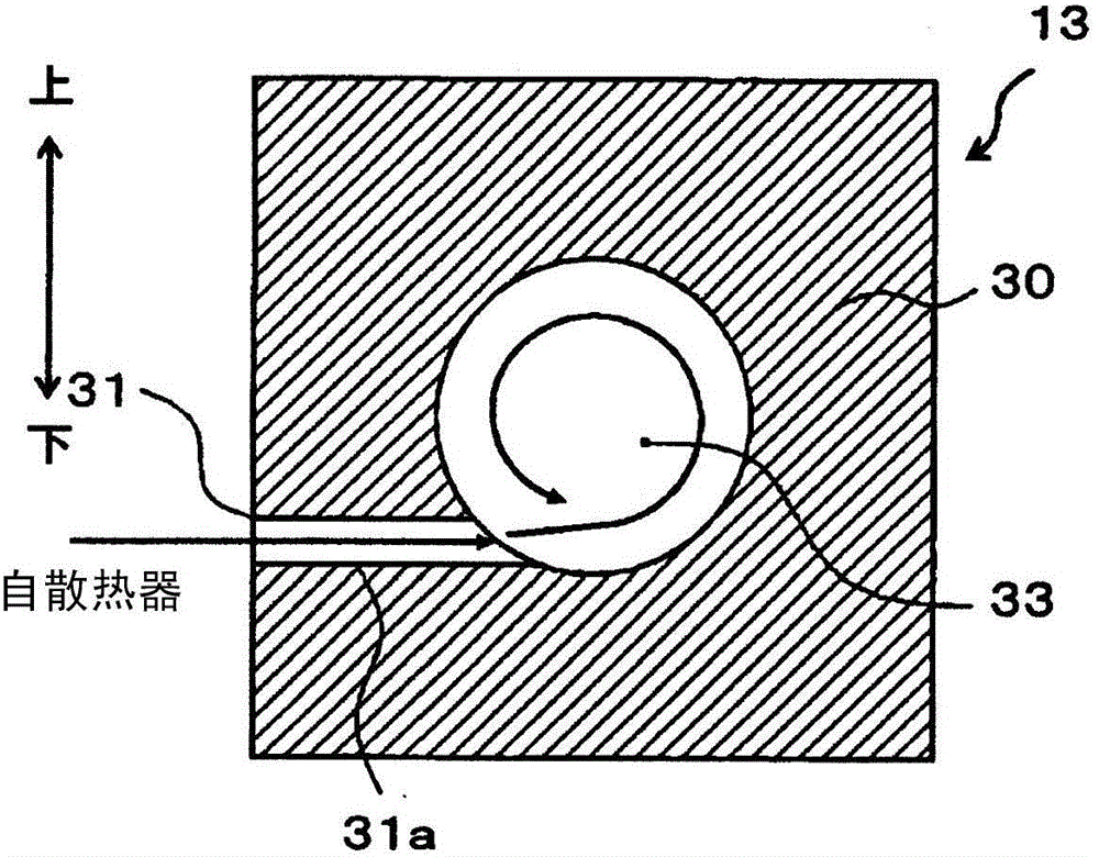
[0033] use Figure 1~3 , the first embodiment of the present invention will be described. Such as figure 1 As shown, the decompression device 13 of this embodiment is applied to the vapor compression refrigeration cycle system 10 . Further, this refrigeration cycle system 10 is applied to a vehicle air-conditioning apparatus, and functions to cool blown air blown into a vehicle interior as a space to be air-conditioned.

[0034] First, in the refrigeration cycle system 10, the compressor 11 is a device that sucks in a refrigerant, pressurizes it to become a high-pressure refrigerant, and discharges it. Specifically, the compressor 11 of the present embodiment is an electric compressor configured by accommodating a fixed-capacity compression mechanism 11 a and an electric motor 11 b that drives the compression mechanism 11 a in a single casing.

[0035] Various compression mechanisms, such as a scroll type compression mechanism and a vane type compression mechanism, can be e...

no. 2 approach

[0074] In the first embodiment, an example in which the valve element 35 formed in a conical shape is used as the valve element of the decompression device 13 was described, but in this embodiment, as Figure 4 As shown, a spool 35a formed in a spherical shape is employed. It should be noted that, in Figure 4 In , the same symbols are attached to the same or equivalent parts as those in the first embodiment. This also applies to the following drawings.

[0075] In addition, a cylindrical space (straight line portion) is formed on the passage forming member 30c disposed on the outer peripheral side of the valve body 35a to form the most upstream part of the refrigerant passage space 34, and the refrigerant flows continuously from the cylindrical space. A truncated conical space (taper) that expands in diameter. And, in this embodiment, if Figure 4 As shown, the minimum passage area portion 34a is formed at the connection portion between the straight portion and the tapere...

no. 3 approach

[0079] In the first embodiment, the decompression device 13 that electrically displaces the actuating rod 36 and the valve body 35 by the electric actuator 37 was described, but in this embodiment, An example of mechanically displacing the operating rod 36 and the valve body 35c. More specifically, as Figure 6 As shown in the cross-sectional view of , the decompression device 13 of this embodiment is configured as a so-called internal pressure equalizing type temperature type expansion valve.

[0080] First, in the main body part 30 of this embodiment, in addition to the aforementioned refrigerant inlet 31, refrigerant outlet 32, etc., a second refrigerant inlet passage 31b through which the low-pressure refrigerant flowing out of the evaporator 14 flows is formed. , and the second refrigerant outflow passage 32 b through which the evaporator 14 outflow refrigerant flowing in from the second refrigerant inflow passage 31 b flows out to the suction side of the compressor 11 ....


PUM


Abstract

A rotation space (33) in which a refrigerant that has flowed in from a refrigerant inflow port (31) rotates, a restriction space (34b) that depressurizes the refrigerant that has flowed out from the rotation space (33), and a downstream-side space (34c) arranged on the refrigerant flow downstream side of the restriction space (34b) and formed such that the internal refrigerant pressure becomes uniform are formed in a body section (30) of a decompression device (13). As a result, causes of noise generation can be suppressed, said causes arising as a result of the refrigerant which has the pressure thereof reduced in the rotation space (33) being caused to flow into the restriction space (34b) and boiling delay occurring. In addition, shock waves caused by reduction in refrigerant pressure can be dampened inside the downstream-side space (34c), and noise during the refrigeration cycle caused by propagation of the shock waves downstream in the decompression device can be suppressed. In other words, the causes of noise generation in the decompression device applied to a vapor compression-type refrigeration cycle can be suppressed.

Description

[0001] This application claims the priority based on the Japanese patent application 2012-140773 for which it applied on June 22, 2012, The indication of the said Japanese patent application is incorporated in this application by reference. technical field [0002] The invention relates to a decompression device suitable for a vapor compression refrigeration cycle system. Background technique [0003] Conventionally, Patent Document 1 discloses a device in which an ejector is connected to a refrigerant outlet of a temperature type expansion valve as a pressure reducing device suitable for a vapor compression type refrigeration cycle. [0004] In the decompression device of Patent Document 1, the pressure of the refrigerant depressurized and boiled by passing through the throttling passage of the thermal expansion valve is restored at the inlet of the nozzle part of the injector, and boiling is generated in the refrigerant flowing into the nozzle part. Nucleation, thereby pro...

Claims


Application Information

Patent Timeline
Patent Type & Authority Applications(China)
IPC IPC(8): F25B41/06F16K1/32F16K47/02
CPCF25B2500/13F25B2341/0683F25B41/06F25B41/062F25B2341/0653F25B2500/12Y02B30/72F16K1/32F16K47/026F25B41/35F25B41/335Y02B30/70
Inventor 阿波良子山田悦久西岛春幸高野义昭
Owner DENSO CORP
Why Eureka
Try Eureka