Gas circuit breaker
A gas circuit breaker and airtight box technology, which is applied to high-voltage air circuit breakers, circuits, electrical components, etc., can solve the problems of surface damage and damage of the insulating operating rod, and the decrease of the surface resistance of the insulating operating rod, so as to meet the requirements of insulation performance, cost reduction effect
- Summary
- Abstract
- Description
- Claims
- Application Information
AI Technical Summary
Problems solved by technology
Method used
Image
Examples
Embodiment approach 1
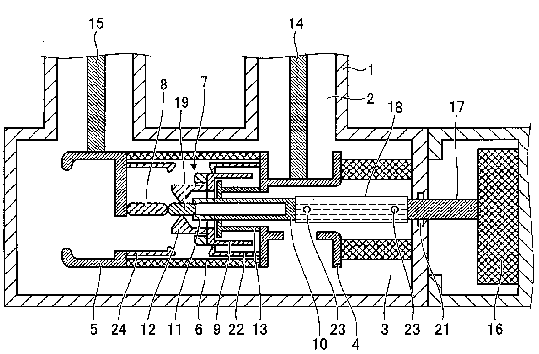
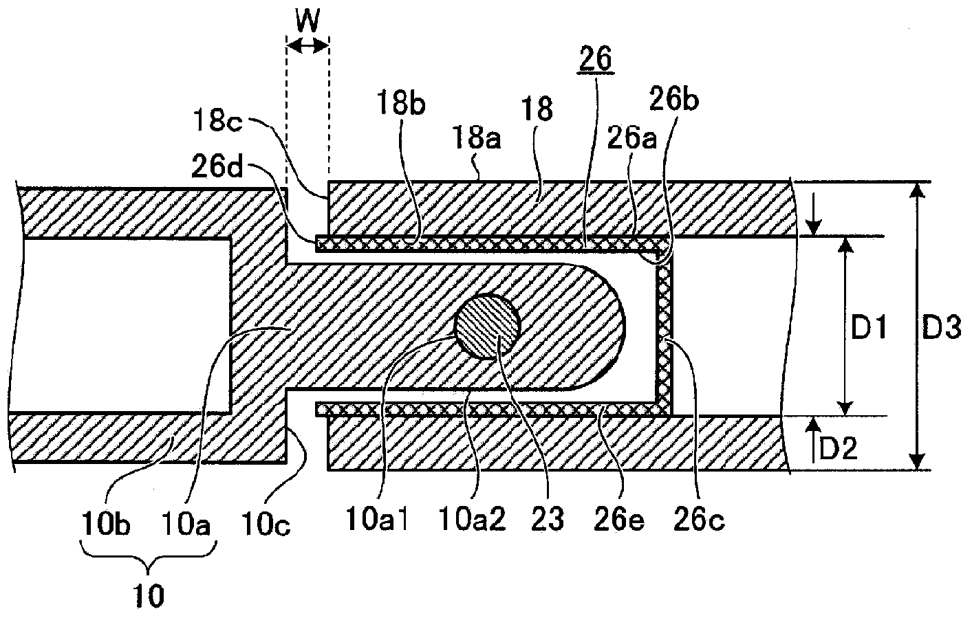
[0023] figure 1 is a longitudinal sectional view showing the structure of the gas circuit breaker, figure 1 An example of a gas circuit breaker to which the gas blocking member according to Embodiments 1 to 5 of the present invention can be applied is shown in . figure 2 It is a figure which shows the gas blocking member concerning Embodiment 1 of this invention. figure 1 The airtight box 1 shown is filled with SF 6 Insulating arc extinguishing gas 2, the gas jet breaking part 7 for cutting off the current is composed of: a fixed contact 8 electrically connected to the fixed side frame 5, and a movable contact 11 opposite to the fixed contact 8 on the same axis , an air spray cylinder 9, an insulator nozzle 12 fixed to the air spray cylinder 9, and a piston 13 fixed to the movable side frame 4.
[0024] The movable side frame 4 is supported by an insulating support cylinder 3 provided inside the airtight case 1 , and the fixed side frame 5 is supported by the movable side ...
Embodiment approach 2
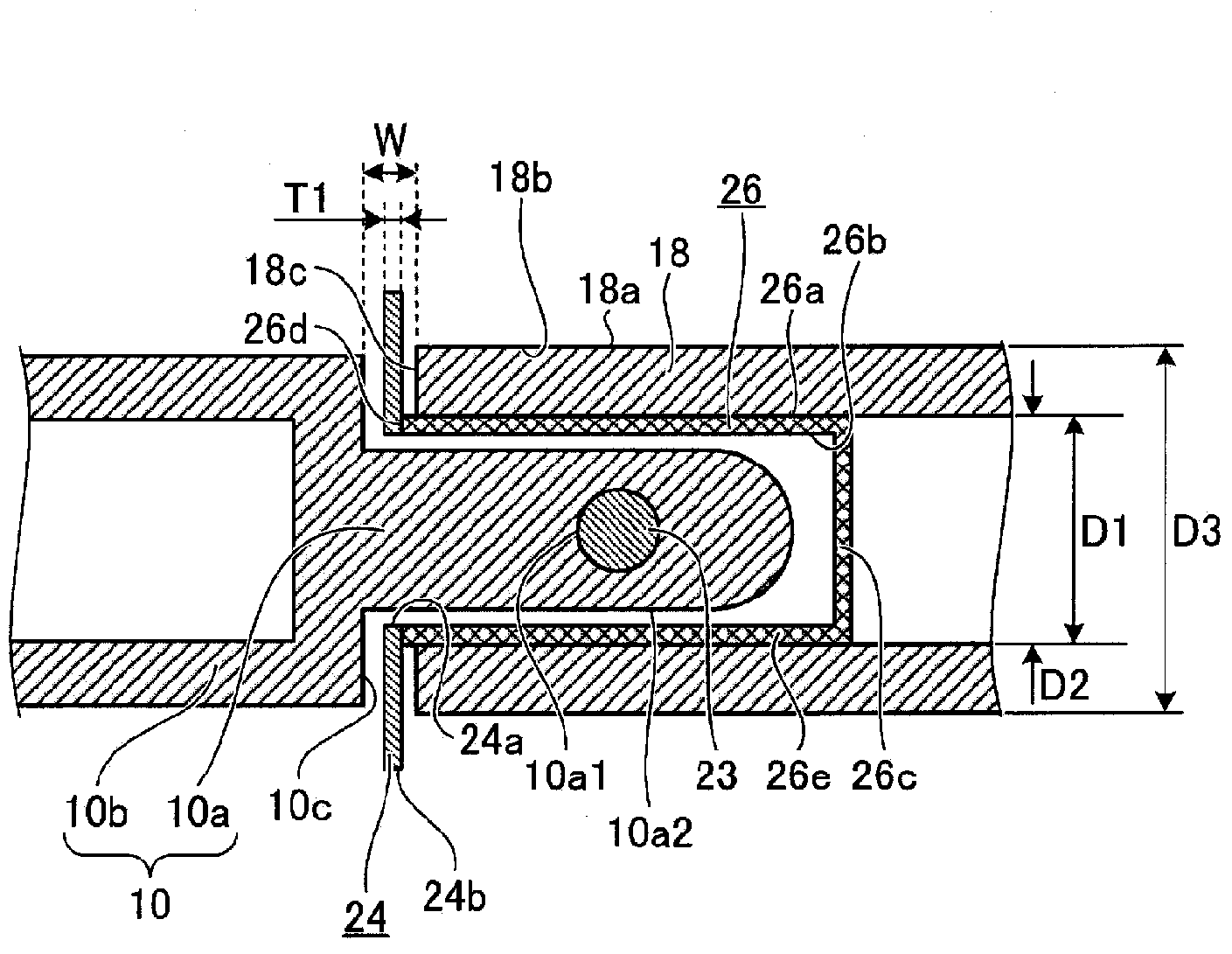
[0040] image 3 It is a figure which shows the gas blocking member concerning Embodiment 2 of this invention. The difference from Embodiment 1 is that the annular member 24 is provided between the opening end side end surface 26d and the axial end surface 10c. Hereinafter, the same reference numerals are assigned to the same parts as those in Embodiment 1, and descriptions thereof will be omitted, and only different parts will be described here.
[0041] The annular member 24 is in the shape of an annular plate, and the inner diameter of the inner peripheral surface 24 a is formed to be larger than the diameter of the small diameter portion 10 a and smaller than the inner diameter D1 of the rod 18 . The outer diameter of the outer peripheral surface 24 b of the annular member 24 is formed to a size larger than the outer diameter D3 of the rod 18 , for example. The thickness T1 of the annular member 24 is formed to be a size smaller than the size of the gap W. As shown in FIG...
Embodiment approach 3
[0045] Figure 4 It is a figure which shows the gas blocking member concerning Embodiment 3 of this invention. The difference from Embodiment 2 is that an annular member 24 - 1 is provided instead of the cylindrical member 26 and the annular member 24 . Hereinafter, the same reference numerals are assigned to the same parts as those in Embodiment 2, and their descriptions are omitted, and only the different parts will be described here.
[0046] The annular member 24-1 is made of, for example, an elastic material (fluororesin, etc.) that is less elastic than the rod 18, and the inner diameter of the inner peripheral surface 24a-1 is formed to be substantially the same as the diameter of the outer peripheral surface 10a2 of the small-diameter portion 10a. size. The outer diameter of the outer peripheral surface 24b - 1 of the annular member 24 - 1 is formed to a size larger than the outer diameter D3 of the rod 18 . The thickness T2 of the annular member 24 - 1 is formed to ...
PUM
 Abstract
Description
Claims
Application Information
 - R&D
- Intellectual Property
- Life Sciences
- Materials
- Tech Scout
- Unparalleled Data Quality
- Higher Quality Content
- 60% Fewer Hallucinations
Browse by: Latest US Patents, China's latest patents, Technical Efficacy Thesaurus, Application Domain, Technology Topic, Popular Technical Reports.
© 2025 PatSnap. All rights reserved.Legal|Privacy policy|Modern Slavery Act Transparency Statement|Sitemap|About US| Contact US: help@patsnap.com


