Supercharge Your Innovation With Domain-Expert AI Agents!

A multi-beam common rail mobile car positioning mechanism

A technology of mobile trolley and positioning mechanism, which is applied in the field of mechanical transmission and connection, can solve the problems of increasing cost, increasing system complexity, increasing system mechanical structure and electrical control, etc., and achieves easy maintenance, reduced manufacturing cost, and accurate beam positioning Effect

Active Publication Date: 2016-04-20
AVIC BEIJING AERONAUTICAL MFG TECH RES INST
View PDF7 Cites 0 Cited by
  • Summary
  • Abstract
  • Description
  • Claims
  • Application Information

AI Technical Summary

Problems solved by technology

[0002] At present, the existing multi-beam structure uses a mobile positioning system with a pair of guide rail mechanisms. Most of them use their own drive mechanisms on each beam. The entire system needs to use multiple sets of drive mechanisms and control systems, which greatly increases It increases the mechanical structure and electrical control of the system, resulting in a large number of repetitive structures and control circuits, which greatly increases the complexity of the system, which not only increases the cost, but also is not conducive to maintenance

Method used


Image

  • A multi-beam common rail mobile car positioning mechanism
  • A multi-beam common rail mobile car positioning mechanism
  • A multi-beam common rail mobile car positioning mechanism

Examples


Embodiment Construction

[0044] The details of the present invention can be understood more clearly with reference to the accompanying drawings and the description of specific embodiments of the present invention. However, the specific embodiments of the present invention described here are only for the purpose of explaining the present invention, and should not be construed as limiting the present invention in any way. Under the teaching of the present invention, the skilled person can conceive any possible modification based on the present invention, and these should be regarded as belonging to the scope of the present invention.

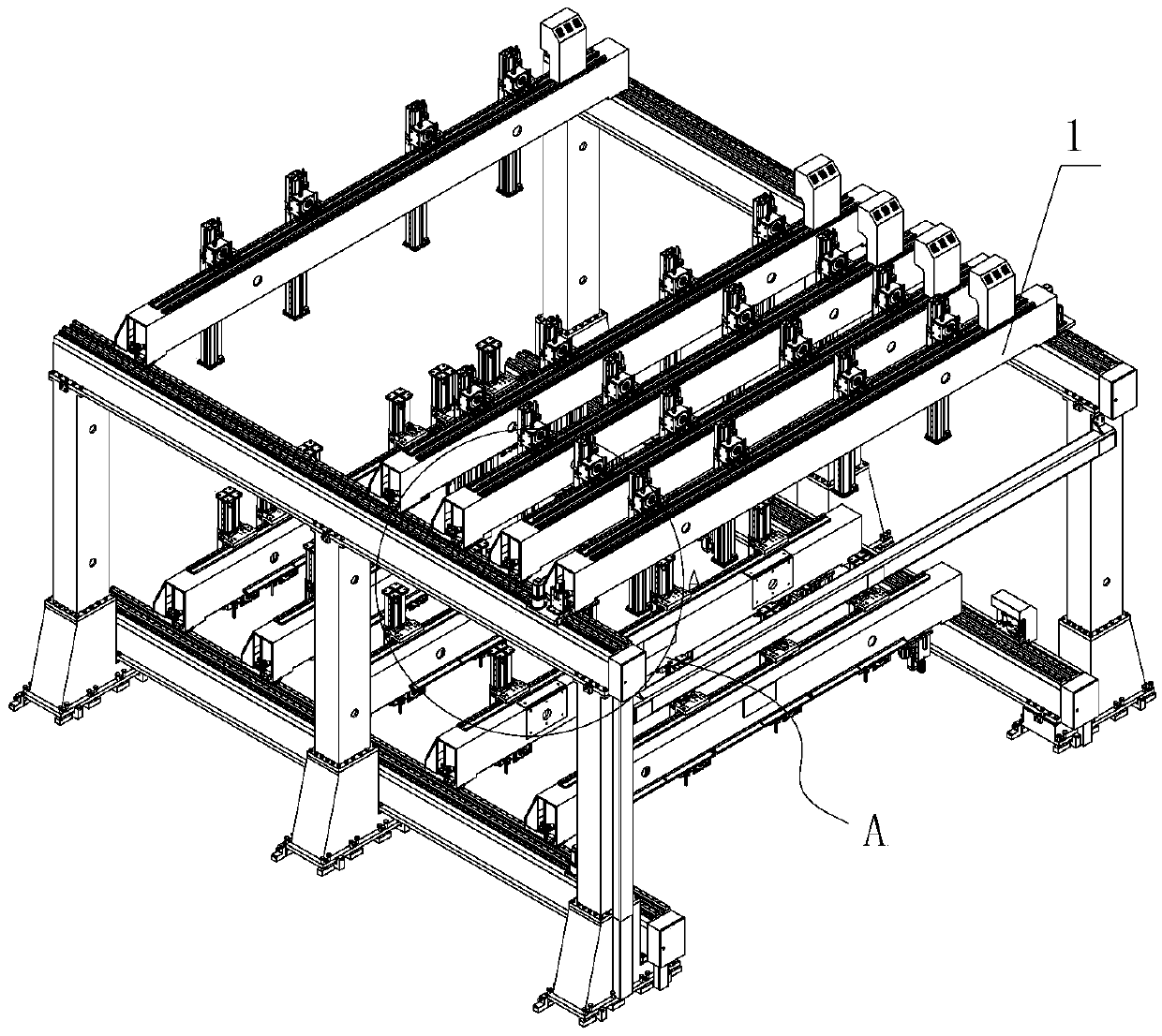
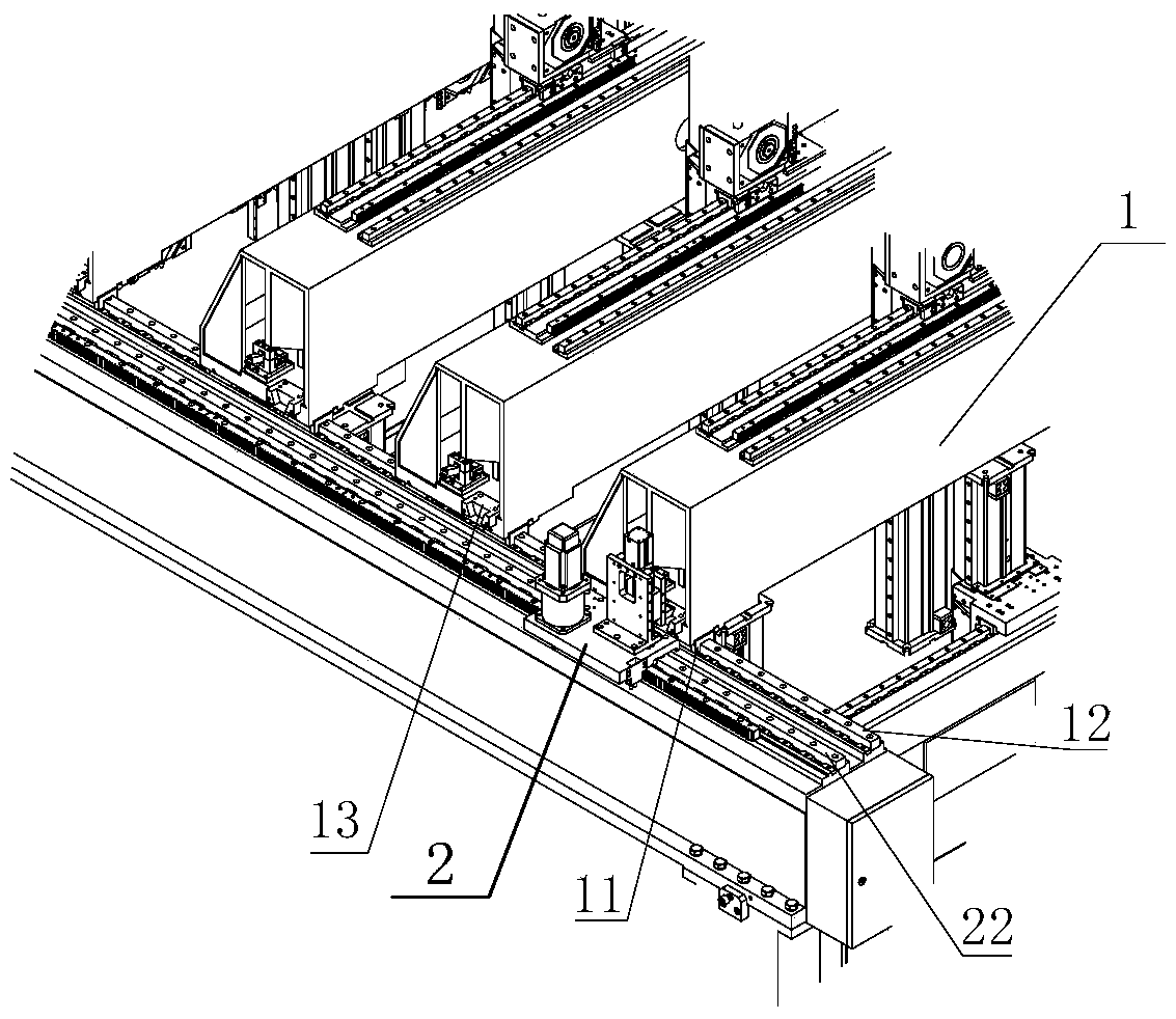
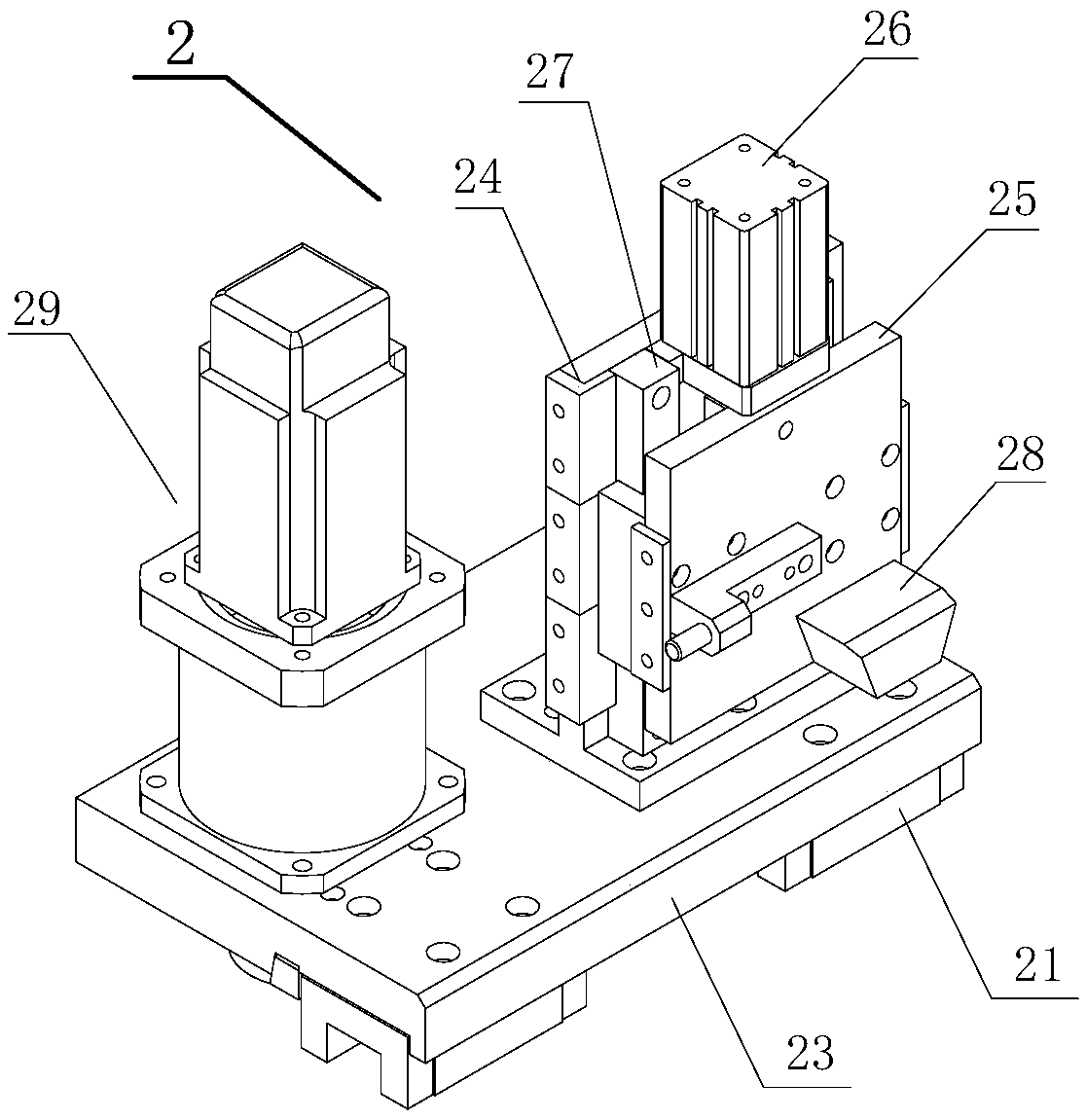
[0045] Please refer to Figure 1 to Figure 10 , figure 1 It is a schematic diagram of the present invention when the multi-beam common rail mobile trolley positioning mechanism is used in combination with the crossbeam; figure 2 for figure 1 Schematic diagram of the enlarged structure in part A; image 3 It is a structural schematic diagram of the mobile trolley of t...


PUM


Abstract

The invention discloses a multi-cross-beam common rail moving trolley positioning mechanism, which is arranged at two sides of a plurality of cross beams in side-by-side arrangement, the bottoms of the two ends of each row of cross beams are parallelly provided with cross beam side blocks, cross beam guide rails glidingly matched with the cross beam slide blocks are respectively arranged in positions corresponding to each cross beam slide block, the outer side of each cross beam guide rail is provided with a trolley guide rail parallel to the corresponding cross beam guider rail, a moving trolley is arranged in a way of being glidingly matched with the trolley guide rails, and the moving trolley can be combined with the end part of each cross beam in a separated way and can drive the cross beams to move along the cross beam guide rails. Through the moving of the moving trolley, a plurality of cross beams are respectively driven to move and to realize positioning, the use of a plurality sets of driving mechanisms and a control system is avoided, the manufacturing cost is greatly reduced, and the multi-cross-beam common rail moving trolley positioning mechanism has the advantages that the positioning of the cross beams is accurate, \ firm and reliable, and the maintenance is convenient. The locking function of the cross beams in fixing positions is realized through a cross beam locking device.

Description

technical field [0001] The invention relates to the technical field of mechanical transmission and connection, in particular to a multi-beam common rail moving trolley positioning mechanism. Background technique [0002] At present, the existing multi-beam structure adopts a mobile positioning system with a pair of guide rail mechanisms. Most of them use their own drive mechanisms on each beam. The entire system needs to use multiple sets of drive mechanisms and control systems, which greatly increases The mechanical structure and electrical control of the system are broken, resulting in a large number of repetitive structures and control circuits, which greatly increases the complexity of the system, which not only increases the cost, but also is not conducive to maintenance. [0003] In view of the shortcomings of the above-mentioned prior art, based on years of research, on-site experience and professional knowledge, the inventor actively improved and innovated based on y...

Claims


Application Information

Patent Timeline
Patent Type & Authority Patents(China)
IPC IPC(8): B21D11/22
CPCB21D7/16
Inventor 张书生徐石磊
Owner AVIC BEIJING AERONAUTICAL MFG TECH RES INST
Features
  • R&D
  • Intellectual Property
  • Life Sciences
  • Materials
  • Tech Scout
  • Unparalleled Data Quality
  • Higher Quality Content
  • 60% Fewer Hallucinations
Learn More