Sand mold structure of oil pan casting

A technology for sand molds and castings, applied in the field of sand mold structures, can solve the problems of large heat loss, sand inclusion defects, and pore sand inclusion defects in molten iron, and achieve the effects of improving quality and dimensional accuracy, reducing sand inclusion in molten iron, and improving the quality of molten iron.

Inactive Publication Date: 2015-03-04
KOCEL EQUIP
View PDF6 Cites 1 Cited by
  • Summary
  • Abstract
  • Description
  • Claims
  • Application Information

AI Technical Summary

Problems solved by technology

Disadvantages: 1) The operation is complicated; 2) There are different degrees of shaking of the core during the turning process, and the size is difficult to guarantee; 3) If the core has a slight expansion or size problem during core making, when the core is assembled, the top of the core The edge 2.1 of the molding surface of the door and the edge of the molding surface 2.3 corresponding to the upper cavity will have the possibility of shear friction, such as the attached Figure 5 It shows that the square door part of the casting has sand inclusion defects due to sand rubbing
[0006] Neither of the above two processes can solve the thin-walled sand (slag) and air hole defects on the top surface of the sand mold on the casting. The reasons include the following points: During the pouring process, the molten iron rushes directly into the core, and in severe cases, the sand core is partially washed out. As a result, part of the air and loose sand are involved in the molten iron; as the liquid level rises during the filling process, the greater the degree of scour to the cavity, the greater the heat loss of the molten iron, and the dirtier the molten iron at the liquid surface (sand, slag), resulting in the lowest temperature of molten iron at the top thin wall of the upper sand mold, which is not conducive to the floating of gas and slag, and a large part of the air and slag in the cold molten iron stays on the top surface, resulting in serious sand inclusion defects in the air pores at the top thin wall

Method used


Image

  • Sand mold structure of oil pan casting
  • Sand mold structure of oil pan casting
  • Sand mold structure of oil pan casting

Examples


Embodiment Construction

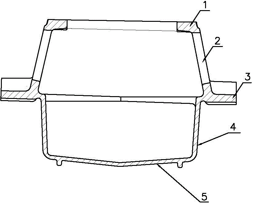
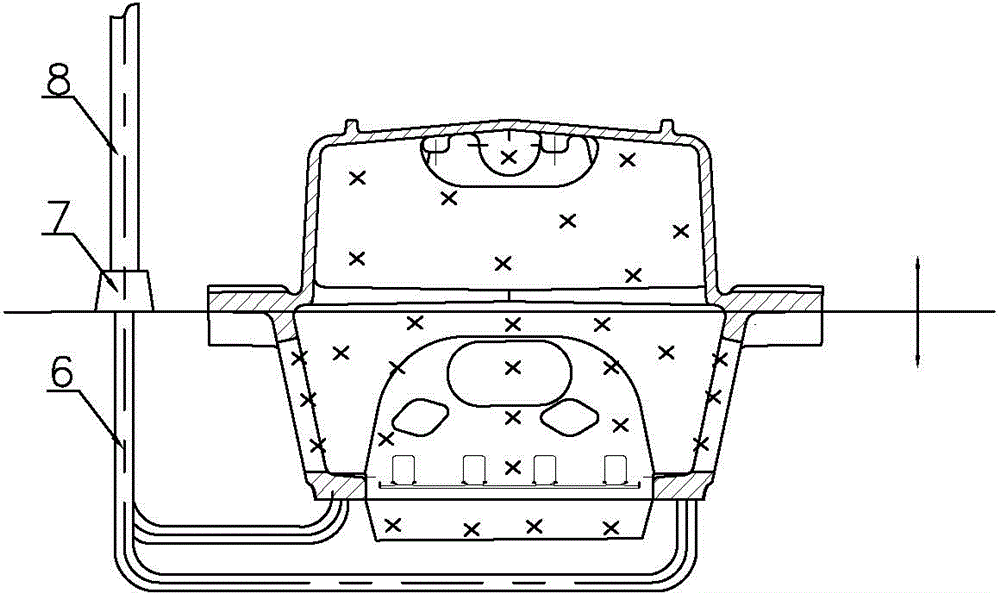
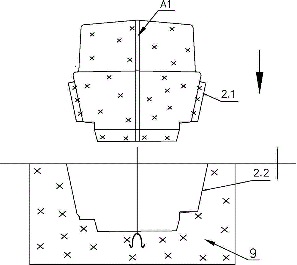
[0020] like Image 6 and Figure 7 Shown is the sand mold structure of the oil pan casting of the present invention, the sand mold of the oil pan casting includes an upper sand mold 10, a lower sand mold 9 and a core 11, and the corresponding mold cavities of the flange 3 of the oil pan casting are vertically arranged on the upper In the sand mold 10 and the lower sand mold 9, it is equivalent to rotating the mold cavity by 90° relative to the sand mold structure in the prior art. The parting surface 12 of the upper sand mold 10 and the lower sand mold 9 is perpendicular to the molding surface corresponding to the top plane and the bottom surface of the casting. The forming structures corresponding to the square doors 2 on the two side walls of the pan casting are respectively arranged on the upper side of the upper sand mold 10 and the lower side of the lower sand mold 9. The mold gating system of the oil pan casting adopts the bottom gating system, including sprue 8, horizon...


PUM


Abstract

The invention relates to a sand mold structure of an oil pan casting, belonging to the technical field of casting. The sand mold structure comprises an upper sand mold, a lower sand mold and a mold core, wherein cavities corresponding to flange plates of the oil pan casting are vertically arranged in the upper sand mold and the lower sand mold respectively; the parting surfaces of the upper sand mold and the lower sand mold are vertical to the forming surfaces corresponding to the top plane and the bottom surface of the casting respectively; forming structures corresponding to square doors on two side walls of the oil pan casting are correspondingly arranged on the upper side of the upper sand mold and the lower side of the lower sand mold, respectively; a section mold pouring system of the oil pan casting adopts a bottom pouring system which comprises a sprue, a cross gate and an ingate, and the inlet of the ingate is formed in the bottom side of a flange cavity of the lower sand mold. According to the sand mold structure of the oil pan casting, the defects of sand inclusion and pores existence at the thin wall of the casting can be effectively avoided by changing the positions of the parting surfaces of the mold and the angle of the rotating cavity, and thus the quality and the dimensional precision of the oil pan casting can be improved.

Description

technical field [0001] The invention relates to the field of casting technology, in particular to a sand mold structure of oil pan castings. Background technique [0002] Oil pan castings are the oil storage parts of internal combustion engines, which have high requirements on air tightness and pressure resistance, and need to be tested for leakage and air tightness. The main structure of oil pan castings is as follows: figure 1 As shown, there is an oil chamber similar to a cuboid, which is mainly surrounded by top 1, side wall 4 and bottom 5, and the bottom 5 and side wall 2 are both thin-walled structures, especially the bottom 5 is a large plane with thin walls, and the side There is an outwardly protruding flange plate 3 in the middle of the outer periphery of the wall 4, square doors 2 are respectively provided on the two side walls of the upper part of the oil chamber, and an opening is arranged on the top of the upper mouth of the oil chamber. [0003] In the casti...

Claims


Application Information

Patent Timeline
Patent Type & Authority Applications(China)
IPC IPC(8): B22C9/02B22C9/08B22C9/24
CPCB22C9/02B22C9/08B22C9/20B22C9/24
Inventor 马林刘利平周杰
Owner KOCEL EQUIP
Why Eureka
Try Eureka