Power chuck for turning hub

A wheel hub and power technology, applied in the field of power chucks for wheel hub turning, can solve the problems of affecting the machining efficiency of machine tools, heavy load, and difficulty in further increasing the spindle speed, so as to prolong the overhaul period and service period, improve service life, and surface The effect of smoothness improvement

Inactive Publication Date: 2015-03-04
吴行飞
View PDF7 Cites 6 Cited by
  • Summary
  • Abstract
  • Description
  • Claims
  • Application Information

AI Technical Summary

Problems solved by technology

At present, there are mainly two types of support structures for power chucks used in wheel hub turning. One is that the support ring cylinder is supported on the outer ring of the upper plate, and the upper plate forms a closed oblate cylinder structure with the support ring cylinder and the chassis. One form is introduced in the patent CN102205428A. The other is that the support ring cylinder is supported in the ring position in the middle of the upper plate, that is, the central axis of the upper plate coincides with the central axis of the support ring cylinder, and the diameter of the upper plate is larger than the outer circle of the support ring cylinder. Diameter, it is a non-closed structure, please refer to the attached drawing of the manual for details figure 1 As shown, the power chucks of these two supporting structures are overall heavy. During processing, the chuck and the hub rotate together at high speed, and the load is heavy, which has a great adverse effect on the service life of the machine tool spindle bearing. It will be overhauled in two years, and it is difficult to further increase the spindle speed, which will affect the machining efficiency of the machine tool

Method used


Image

  • Power chuck for turning hub
  • Power chuck for turning hub
  • Power chuck for turning hub

Examples


Embodiment Construction

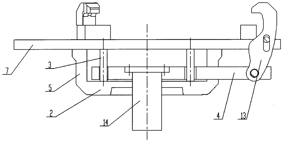
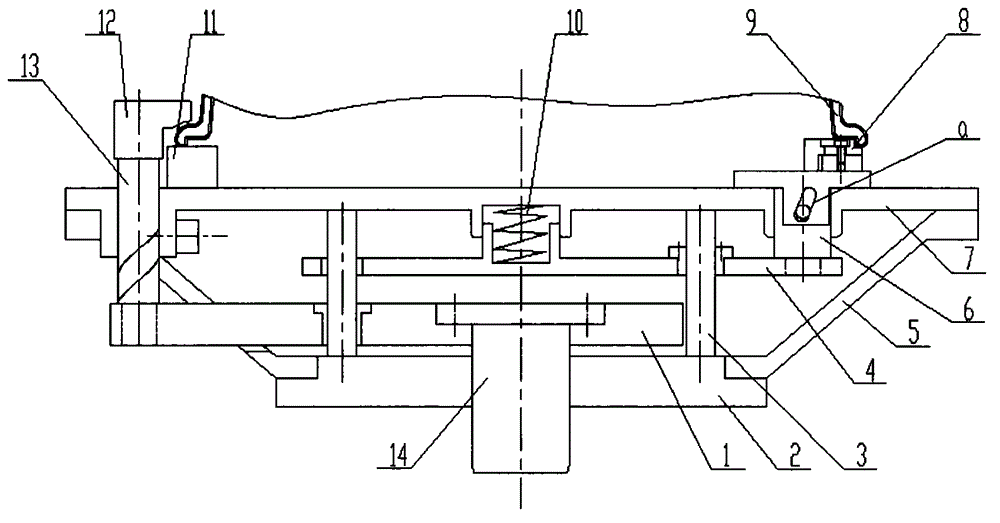
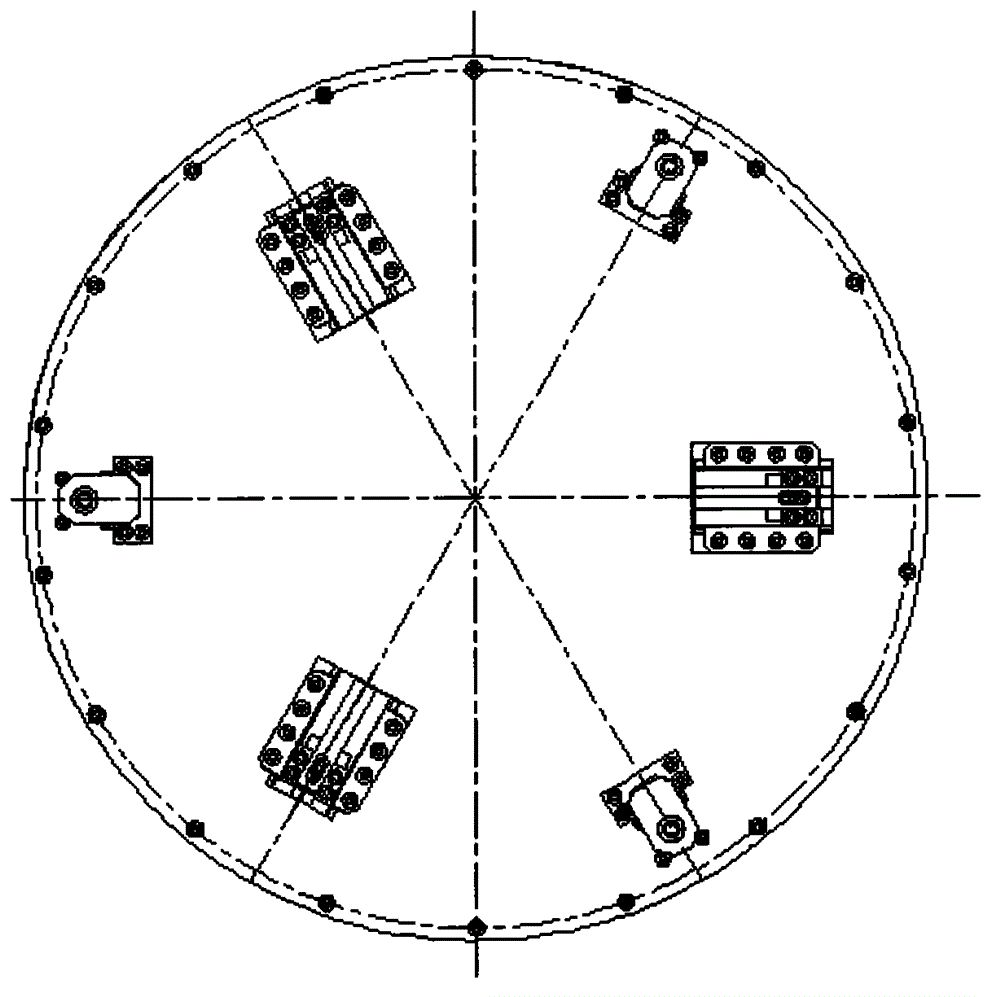
[0018] like Figure 2 to Figure 4 As shown, the wheel hub turning power chuck of the present invention is composed of a chassis 2, a support ring 5, a support guide rod 3 and an upper plate 7 to form its support structure, and the relative position of the chassis 2 and the upper plate 7 is formed by the support ring 5 and the support guide rod. 3 is fixed, and the central positioning frame 4 and the pressing claw pressing the connecting frame 1 are guided by the supporting guide rod 3 and can only move in the axial direction.

[0019] After the wheel hub is put in, the oil cylinder pulls the drive cylinder connecting shaft 14 to move downward, and the drive cylinder connecting shaft 14 is connected with the pressing claw pressing connecting frame 1, so that the pressing claw pressing connecting frame 1 moves downward, and the connecting frame 1 connected with it The axial pressing mechanism 13 makes the pressure claw 12 move downwards and also rotates around its own axis, so t...


PUM


Abstract

The invention provides a power chuck for turning a hub which comprises a chassis, an upper plate, a support ring, a support guide rod, a pressing claw compression connecting rack, a central positioning rack, an axial compressing mechanism, a radial automatic positioning mechanism, a driving cylinder connecting shaft, a spring and the like. The power chuck has the characteristics that the annular conical support structure is adopted, so that the overall weight of the power chuck for turning the hub is greatly reduced, the main shaft load of a machine tool is reduced, the overhaul period and service life of the machine tool are prolonged and the utilization ratio of the machine tool is improved; furthermore, the rotation speed of the main shaft of the machine tool is favorably increased, so that the processing time of each hub can be shortened and the production efficiency is improved.

Description

technical field [0001] The invention relates to a power chuck for wheel hub turning, which belongs to the field of wheel hub machining tooling equipment. Background technique [0002] With the rapid increase of car ownership and the acceleration of car replacement, the demand for car wheels is also increasing sharply. It is the wheel hub manufacturers' consistent The pursuit of the wheel hub turning power chuck has an important impact on the wheel hub processing time, positioning accuracy, machine speed, machine tool maintenance cycle, and the production efficiency and production cost of the wheel hub. It is the key tooling equipment for wheel hub processing. [0003] The power chuck for wheel hub turning requires the hub to be automatically centered and positioned after the hub is placed in the station, and quickly pressed. During processing, the power chuck and the clamped hub rotate at high speed together. After processing, it must be released quickly to facilitate unload...

Claims


Application Information

Patent Timeline
Patent Type & Authority Applications(China)
IPC IPC(8): B23B31/30
CPCB23B31/302
Inventor 吴行飞李全贵邓崛华曹光有邓光亚
Owner 吴行飞
Why Eureka
Try Eureka