Adsorber

A technology of adsorber and body, which is applied in the direction of manipulators, chucks, manufacturing tools, etc., can solve the problems of destroying fluid flow state, unstable suction force, providing friction force, etc., and achieve the effect of avoiding flow disorder and benefiting suction force

Inactive Publication Date: 2016-07-20
杭州孚亚科技有限公司
View PDF5 Cites 0 Cited by
  • Summary
  • Abstract
  • Description
  • Claims
  • Application Information

AI Technical Summary

Problems solved by technology

[0004] 1) if Figure 4 As shown, the fluid entering the cylindrical cavity from the nozzle 2 will be discharged from the bottom of the suction cup. Therefore, the suction cup will keep a certain distance from the object while sucking up the object below, and the fluid flows into the gap and flows through the gap Discharge, which results in no contact between the suction cup and the object, so the suction cup cannot provide friction to the object in the lateral direction
Without lateral friction, the object cannot follow the suction cup to move laterally
[0005] 2) When the fluid flows through the gap flow channel between the bottom surface of the outer edge of the suction cup and the object, under the action of viscosity, a high pressure distribution higher than the pressure of the peripheral environment will be formed in the gap flow channel, see Figure 5 , the high pressure distribution will not only exert a repelling force on the workpiece below, but also make the low pressure distribution in the cylinder cavity move to the high pressure direction, all of which lead to the weakening of the suction force
[0006] 3) When the surface of the object below is rough or uneven, the flow resistance of the gap flow channel formed by the surface of the object and the bottom surface of the outer edge of the suction cup will increase, and the flow resistance is irregular in the circumferential direction, that is, in some places The flow resistance is large, and the flow resistance in some places is small, so the fluid is disturbed when it flows through such a flow channel, see Image 6 , these factors lead to a sharp drop in suction and the adsorption becomes unstable
According to our research, there is a linkage relationship between the high pressure distribution in the gap flow channel of the suction cup and the low pressure distribution in the cavity, that is to say, if the high pressure distribution in the gap flow channel becomes disordered, the low pressure distribution in the cavity will also change. In addition, if the surface of the object becomes rough, the resistance of the fluid flowing through the gap flow channel will increase, and the high pressure distribution of the gap flow channel will increase, and the repulsive force acting on the object will increase. will increase, and the increased high-pressure distribution will also make the low-pressure distribution in the cavity move to the high-pressure direction, and the final result is a sharp decrease in suction
[0007] 4) When the object is a soft material, the object deforms under the low pressure in the cavity, causing the center part to sink into the cavity. Such deformation is likely to cause local contact between the object and the suction cup. See Figure 7 , the fluid cannot be discharged from the part where local contact occurs, which leads to a serious asymmetry in the discharge of the fluid in the circumferential direction, and confusion will occur when the fluid is discharged. Such asymmetric discharge and confusion will destroy the flow of the fluid rotation in the cylindrical cavity state, the result is a substantial drop in suction

Method used


Image

  • Adsorber
  • Adsorber
  • Adsorber

Examples


Embodiment Construction

[0030] Below in conjunction with accompanying drawing example, the present invention is described in further detail:

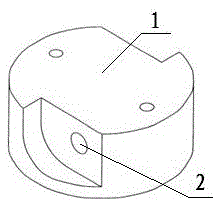
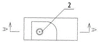
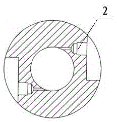
[0031] Such as Figure 8 with Figure 9 The illustrated embodiment includes a body 11, which has a circular cavity 11-1 with a circular cross section. The cavity 11-1 has a closed end face and an open end face, and the open end face forms an end face for absorbing objects. On the inner wall of 11, there is a tangentially arranged nozzle 12 that communicates with the fluid supply source inside and outside the cavity 11-1. The fluid ejected from the nozzle generates a swirling flow inside the cavity 11-1. There can be one or more nozzles One, distributed equidistantly along the circumferential direction of the cylindrical cavity, the body 11 is provided with an annular bottom plate 13 below it, and a top plate 14 is arranged above it, and the annular bottom plate 13 and the top plate 14 are arranged on the two side walls of the body 11 The two connecting rods ...


PUM


Abstract

The invention discloses an adsorber. The adsorber comprises a body; a cavity with the round cross section is arranged in the body; the cavity is provided with a closed end face and an opened end face; an end face for adsorbing an object is formed by the opened end face; a nozzle which is arranged in the tangent direction and communicated with the cavity and an external fluid supply source is arranged on the inner wall of the cavity; an annular bottom plate is arranged below the body through a connecting part; a gap is reserved between the annular bottom plate and the lower end face of the body; a discharging flow way is formed by the gap; and the discharging flow way is communicated with the interior and the peripheral environment of the cavity. The adsorber can adsorb the flexible object with the rough and uneven surface; and in transverse carrying process, the object cannot slide and fall off.

Description

technical field [0001] The present invention relates to an adsorber. Background technique [0002] In the industrial automation production line, we often need to perform handling operations on objects with rough and uneven surfaces or soft materials. Such operations are especially important in operations such as object packing, arrangement, and workpiece screening. How to grab such an object is a technical problem. At present, the commonly used method is to use claw-shaped manipulators. However, the cost of claw-shaped manipulators is high, the failure rate of the mechanical structure is high, the daily maintenance is complicated, and it cannot be applied to some flaky and soft objects. Using a vacuum chuck is another commonly used method. The vacuum chuck is connected to a vacuum source (vacuum pump or jet vacuum generator) to generate vacuum and suction by sucking the air between the vacuum chuck and the object. However, the vacuum chuck is The objects that can be adsorb...

Claims


Application Information

Patent Timeline
Patent Type & Authority Patents(China)
IPC IPC(8): B25J15/00
Inventor 黎科
Owner 杭州孚亚科技有限公司
Why Eureka
Try Eureka