Boom type full hydraulic concrete automatic feeding mixing and feeding integrated system
What is Al technical title?
Al technical title is built by PatSnap Al team. It summarizes the technical point description of the patent document.
An automatic feeding and concrete technology, which is applied in the direction of mixing plant, cement mixing device, liquid batching supply device, etc., can solve the problems of high labor intensity, long time-consuming, inconvenient operation, etc., and achieve high degree of automation and reasonable structure design , mobile flexible and convenient effect
Active Publication Date: 2016-08-24
湖南鼎峰机械有限公司
View PDF8 Cites 0 Cited by
Summary
Abstract
Description
Claims
Application Information
AI Technical Summary
This helps you quickly interpret patents by identifying the three key elements:
Problems solved by technology
Method used
Benefits of technology
Problems solved by technology
[0003] The shortcomings of the above three construction methods are: the first method requires many personnel, occupies a large area, has low efficiency, poor concrete construction quality, high labor intensity, high cost, and requires places with electricity, and the equipment cannot be moved easily. Convenience, high transportation costs; the second method requires a lot of equipment, high energy consumption, large floor area, manual piping, high labor intensity, long time-consuming, low efficiency, high cost, inconvenient operation, complicated maintenance, It also needs a place with electricity, the equipment is very inconvenient to move, and the transportation cost is high. It is not suitable for places with narrow sites, field operations and places without electricity; the third method is not suitable for field operations, rural narrow places and places where the amount of concrete is small. place, and the cost is high, the cost is high
Method used
Image
Click on the blue label to locate the original text in one second.
Reading with bidirectional positioning of images and text.
Examples
Embodiment Construction
[0036] Attached to the invention Figure 1-11 The tags are as follows:
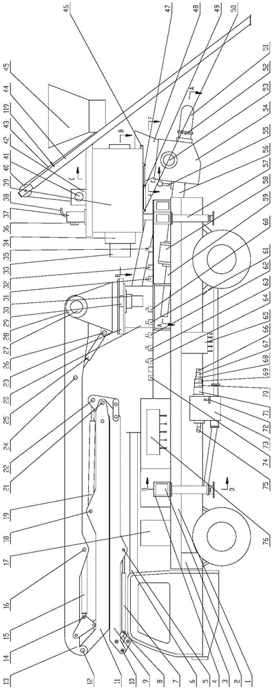
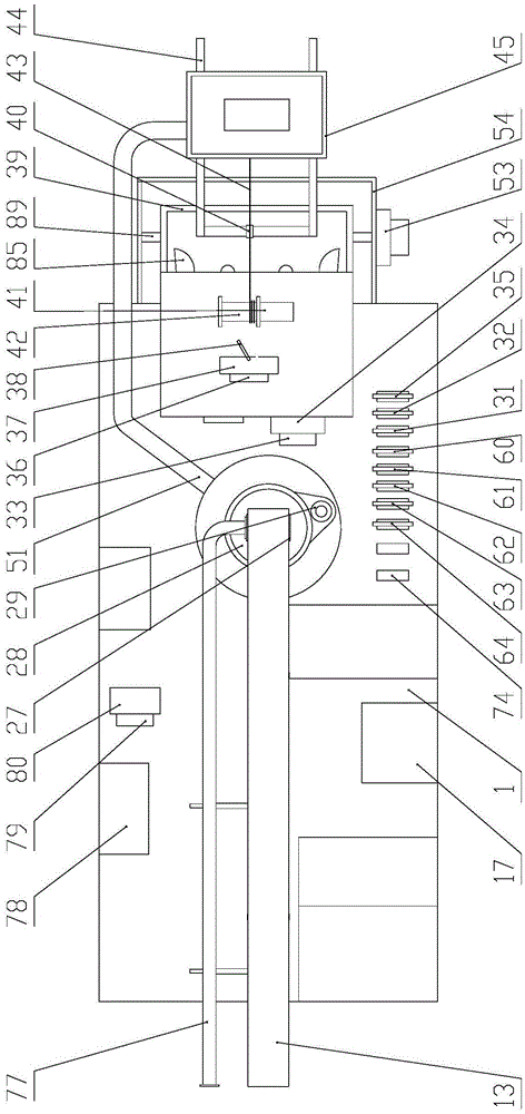
[0037] 1 is a frame, 2 is a telescopic square tube (including 4), 3 is an automobile chassis, 4 is a fixed square tube (including 4), 5 is the pin shaft 1 of the fourth joint oil cylinder, and 6 is the fourth joint arm, 7 is the fourth arm oil cylinder, 8 is the fourth arm oil cylinder pin II, 9 is the third arm, 10 is the fourth arm pin, 11 is the second arm, 12 is the second arm pin , 13 is the first section arm, 14 is the second section arm oil cylinder pin II, 15 is the second section arm oil cylinder, 16 is the second section arm oil cylinder pin I, 17 is the oil tank, 18 is the third section arm oil cylinder pin Axis I, 19 is the oil cylinder of the third section arm, 20 is the slewing support seat, 21 is the pin shaft of the third arm frame, 22 is the pin shaft II of the oil cylinder of the third section arm, 23 is the slewing bearing, and 24 is the pin of the oil cylinder of the first section arm...
PUM
Abstract
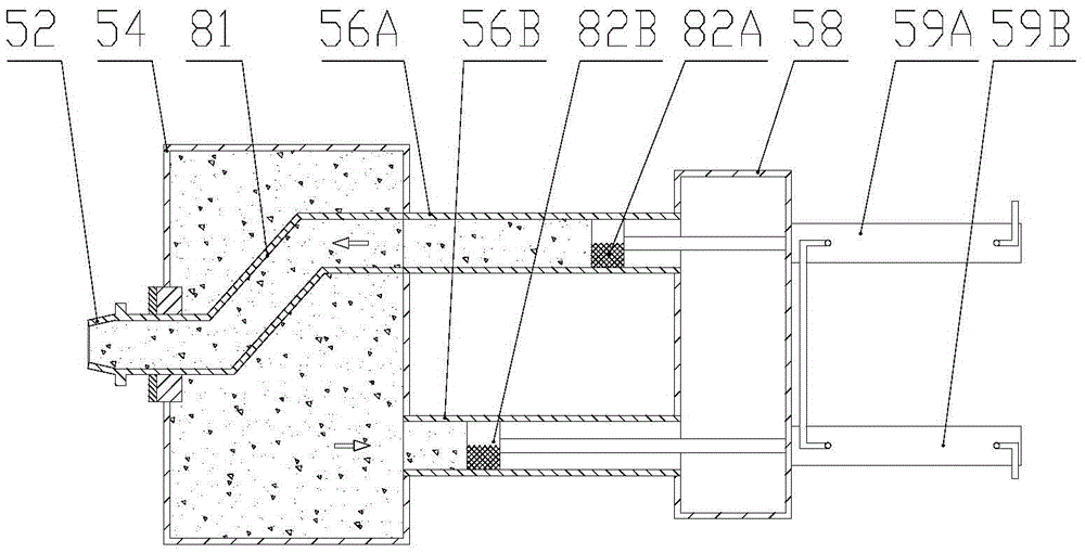
The invention discloses an arm rack type full-hydraulic automatic concrete loading, stirring, conveying and distributing all-in-one system which is designed for mainly solving the problems of low construction quality and high cost of an existing concrete stirring and conveying mode. The arm rack type full-hydraulic automatic concrete loading, stirring, conveying and distributing all-in-one system comprises an automobile chassis, a stander arranged on the automobile chassis, and a loading device, a stirring device, a pumping device, an arm rack device, a cleaning device and an electric control box which are respectively arranged on the stander, wherein the loading device is used for conveying a material to the stirring device; the stirring device is used for conveying the material to the pumping device; the pumping device is used for conveying the material to the arm rack device, and the arm rack device is used for distributing concrete. The arm rack type full-hydraulic automatic concrete loading, stirring, conveying and distributing all-in-one system integrates the functions of automatic loading, continuous forced stirring, pumping, distribution and the like, so that the arm rack type full-hydraulic automatic concrete loading, stirring, conveying and distributing all-in-one system is high in automation degree; the whole arm rack type full-hydraulic automatic concrete loading, stirring, conveying and distributing all-in-one system is arranged on the automobile chassis, moves flexibly and conveniently and is reasonable in structural design, convenient to maintain and low in cost.
Description
technical field [0001] The invention relates to a boom-type full-hydraulic concrete automatic feeding, stirring, and distributing integrated system. Background technique [0002] At present, there are mainly three construction methods for concrete mixing and concrete transportation in urban, rural and field operations, as well as water conservancy construction and other occasions: one is to manually load materials, use a drum mixer or a forced mixer to mix the concrete, and then use a crane to move the concrete. The mixed concrete is hoisted to the required position; the second is to use the drum mixer or forced mixer to mix the concrete through manual feeding, and then use the concrete pump to transport the mixed concrete to the required position; the third is to deliver the commercial concrete with a mixer truck Go to the construction site for concrete mixing, and then use the boom pump truck to transport the mixed concrete to the required location. [0003] The shortcomi...
Claims
Application Information
Patent Timeline
Application Date:The date an application was filed.
Publication Date:The date a patent or application was officially published.
First Publication Date:The earliest publication date of a patent with the same application number.
Issue Date:Publication date of the patent grant document.
PCT Entry Date:The Entry date of PCT National Phase.
Estimated Expiry Date:The statutory expiry date of a patent right according to the Patent Law, and it is the longest term of protection that the patent right can achieve without the termination of the patent right due to other reasons(Term extension factor has been taken into account ).
Invalid Date:Actual expiry date is based on effective date or publication date of legal transaction data of invalid patent.