
Die forging stamping single upper cantilever bracket of railway line contact network

A catenary, railway line technology, applied in overhead lines and other directions, can solve the problems of difficulty in reaching a higher level, affecting the safety of trains, high replacement and maintenance costs, reducing replacement and maintenance costs, extending life, and enhancing filling performance. Effect

Inactive Publication Date: 2015-03-04
CHONGQING ZHONGCHENG PRECISION DIE FORGING
View PDF6 Cites 0 Cited by
  • Summary
  • Abstract
  • Description
  • Claims
  • Application Information

AI Technical Summary

Problems solved by technology

[0004] In the prior art, the die-forged and stamped single upper arm base of the railway line catenary is made by forging. During use and related performance testing, its performance is still difficult to reach a high level, at least it cannot adapt to higher vehicles. Due to the requirement of speed, the distance between the top of the two lugs and the base body (bottom plane) of the component is relatively large, forming a large height difference, the filling performance is reduced during forging, and the top of the two lugs is easy to form a correlation Defects, forming defective or waste products; and the connection between the two lugs and the base body is prone to stress concentration and cracks, or even breaks, resulting in short service life, high replacement and maintenance costs, and affecting the safety of the train

Method used


Image

  • Die forging stamping single upper cantilever bracket of railway line contact network
  • Die forging stamping single upper cantilever bracket of railway line contact network
  • Die forging stamping single upper cantilever bracket of railway line contact network

Examples


Embodiment Construction

[0021] The present invention will be described in further detail below in conjunction with the accompanying drawings and specific embodiments.

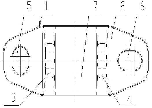
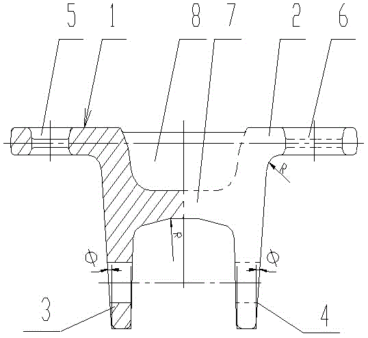
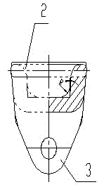
[0022] Such as Figure 1-3 As shown, a single upper wrist arm base of a railway catenary support seat includes a body 1, the body 1 is an integrated die forging, and is formed by die forging at one time; the body 1 is composed of a base body 2 and a first lug 3, a second The two lugs 4 are connected, the axes of the first lug 3 and the second lug 4 are parallel, and the first lug 3 and the second lug 4 are perpendicular to the base body 2; the base body 2 is provided with a first Shaped hole 5 and the second strip-shaped hole 6, the axes of the first strip-shaped hole 5 and the second strip-shaped hole 6 are perpendicular. That is, the length directions of the first strip-shaped hole 5 and the second strip-shaped hole 6 are perpendicular to each other.

[0023] On the base body 2, between the first lug 3 and the second lug 4, a thic...


PUM


Abstract

The invention discloses a die forging stamping single upper cantilever bracket of a railway line contact network. The die forging stamping single upper cantilever bracket of the railway line contact network is one-step molded by integrated die forgings; a main body comprises a base body, and a first support lug and a second support lug which are connected, and are formed on the base body; the first support lug and the second support lug are arranged vertical to the base body; a thickening block is arranged so as to reduce the distance between the top ends of the first support lug and the second support lug and the upper surface of the base body; a first strip hole and a second strip hole are forged by die forging to correspondingly form inner concave pits in the upper surface and the lower surface; an interlayer is formed between the two corresponding inner concave pits in the upper surface and the lower surface, and is removed through stamping to obtain two stamped holes. According to the single upper cantilever bracket, the two support lugs and the base body adopt a die forging one-step mold structure, so that the mechanical properties such as the strength and the rigidity are greatly improved, the self-bearing capacity is enhanced, and the shock resistance is greatly improved; the driving safety factors of high-speed trains are high, so that the requirement on faster high-speed train line safety driving is met.

Description

technical field [0001] The invention relates to an accessory part of a railway catenary support seat, in particular to a die-forging stamping single upper arm base of the railway catenary. [0002] Background technique [0003] As an important part of the railway line catenary, the forging and stamping single upper arm base of the railway line catenary plays an important role in ensuring the safe running of the train. With the increase of railway speed, the train speed has reached 250~350h / km, and there will definitely be higher speed requirements in the future. Therefore, the frequency of catenary oscillations on railway lines will also increase accordingly. Related components put forward higher performance requirements. [0004] In the prior art, the die-forged and stamped single upper arm base of the railway line catenary is made by forging. During use and related performance testing, its performance is still difficult to reach a high level, at least it cannot adapt to ...

Claims


Application Information

Patent Timeline
Patent Type & Authority Applications(China)
IPC IPC(8): B60M1/20
Inventor 顾良
Owner CHONGQING ZHONGCHENG PRECISION DIE FORGING
Learn More