Dehumidifier capable of increasing dehumidifying efficiency

A dehumidifier and efficiency technology, applied in the field of dehumidifiers to improve dehumidification efficiency, can solve the problems of increasing indoor temperature, less air intake, low human comfort, etc., to improve air cleanliness, improve dehumidification efficiency, and avoid indoor temperature. Elevated effect

Active Publication Date: 2015-03-04
张启兵
View PDF6 Cites 4 Cited by
  • Summary
  • Abstract
  • Description
  • Claims
  • Application Information

AI Technical Summary

Problems solved by technology

[0011] The disadvantages of existing dehumidifiers that use drying wheels for dehumidification are: (1) Due to the heat exchange with the regeneration air, the air discharged after dehumidification through the dehumidification flow path has a relatively high temperature, and direct discharge will increase the indoor temperature, which will increase the comfort of the human body. (2) The indoor air to be dehumidified is only sucked from the front of the body, and the air intake is relatively small

Method used


Image

  • Dehumidifier capable of increasing dehumidifying efficiency
  • Dehumidifier capable of increasing dehumidifying efficiency
  • Dehumidifier capable of increasing dehumidifying efficiency

Examples


Embodiment Construction

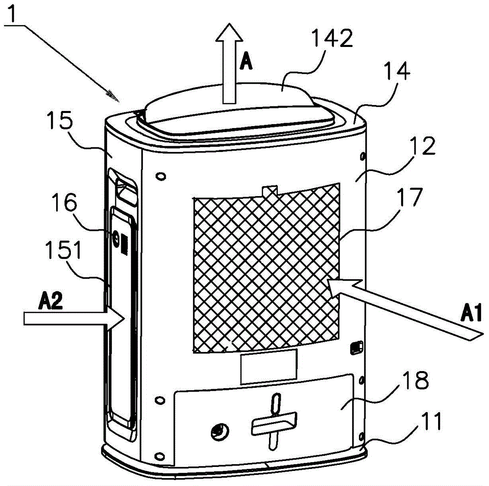
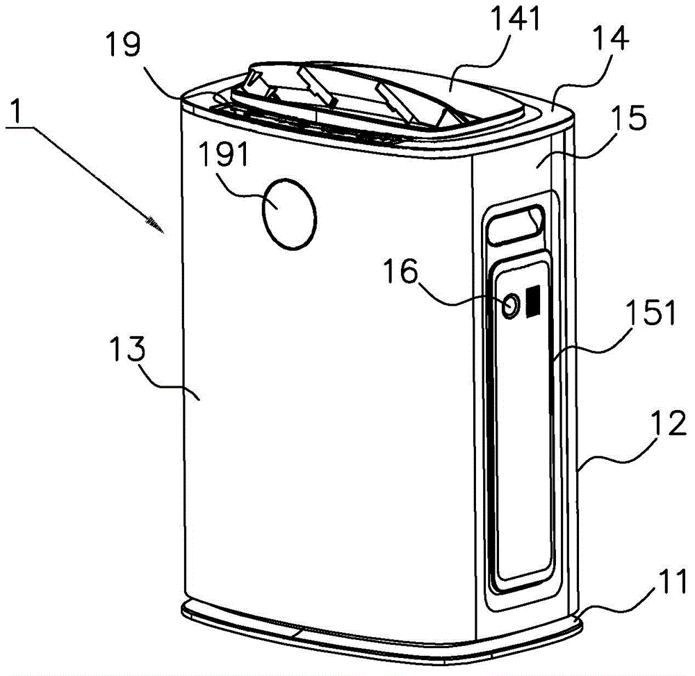
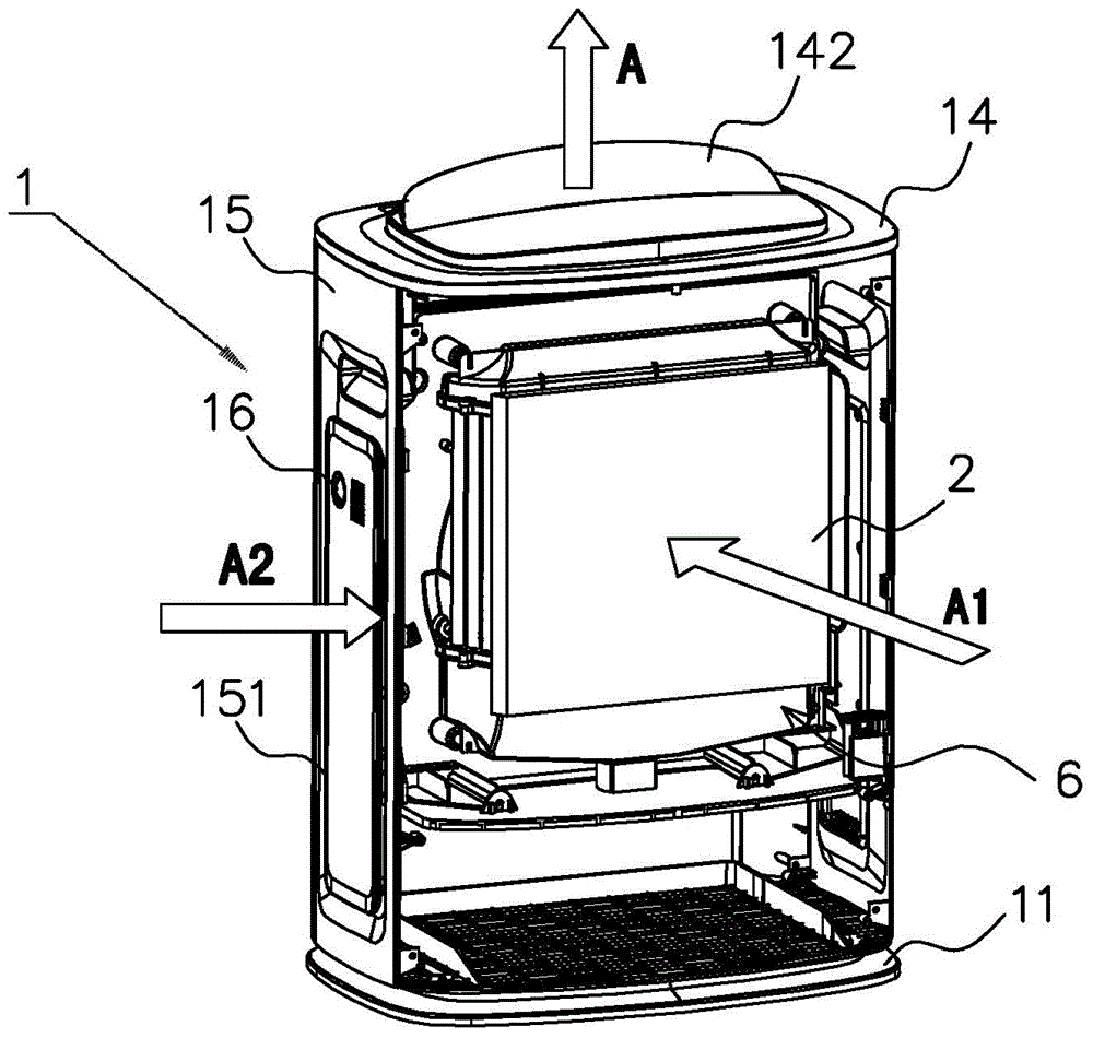
[0050] Such as figure 1 , figure 2 , Figure 5 As shown, a dehumidifier for improving heat exchange efficiency in the present invention includes a body 1, and the body includes: a base 11, a front panel 12 and a rear panel 13 fixed on the base 11, and a top plate connecting the front panel 12 and the rear panel 13 14 and two side panels 15. Wherein, the front panel 12 is provided with a first air inlet 121 , and the first air inlet 121 is covered with a mesh plate 17 . An air outlet 141 is provided on the top plate 14 , and swing blades 142 are installed at the air outlet 141 for adjusting the air flow direction of the air outlet 141 . Also be provided with control part 19 on the top board, be used for operating the operation of dehumidifier, temperature and humidity sensor is installed on the rear panel 13, temperature and humidity sensor has display screen 191, the user operates according to the temperature and humidity information that display screen 191 shows control ...


PUM


Abstract

The invention discloses a dehumidifier capable of increasing dehumidifying efficiency. The dehumidifier comprises a body provided with a first air inlet and an air outlet. A first dehumidifying flow path sequentially passing a condensing heat exchanger and a dehumidifying wheel is formed between the first air inlet and the air outlet. The body is further provided with a second air inlet. A second dehumidifying flow path passing the dehumidifying wheel is formed between the second air inlet and the air outlet. The dehumidifier has the advantages that the second dehumidifying flow path is formed in the dehumidifier on the basis of the conventional first dehumidifying flow path, the indoor air of the second dehumidifying flow path does not pass the condensing heat exchanger and directly passes the dehumidifying wheel, air quantity compensation to the first dehumidifying flow path is achieved to prevent air insufficiency at the first air inlet, the temperature of the second dehumidifying flow path after humidification is lower than the temperature of the first dehumidifying flow path due to the fact that the indoor air of the second dehumidifying flow path does not exchange heat with regenerated air, the air temperature at the air outlet can be lowered relatively during discharging, indoor temperature rising is avoided, and dehumidifying efficiency is increased.

Description

technical field [0001] The invention relates to a dehumidification device, in particular to a dehumidifier with improved dehumidification efficiency. Background technique [0002] According to different working methods, the existing dehumidifiers can be divided into those using a refrigeration cycle and those using a drying wheel. [0003] Among them, dehumidifiers using a refrigeration cycle require a compressor, and there are problems such as compressor noise and ensuring space for arranging the compressor during use. Therefore, dehumidifiers using drying wheels have been widely used in recent years. The working principle of this dehumidifier is that the dehumidification wheel has the property of absorbing moisture in the air. First, the indoor air passes through the dehumidification wheel and is dehumidified and then discharged. [0004] Here, the air for regenerating the desiccant wheel becomes high temperature and high humidity, and the high temperature and high humidi...

Claims


Application Information

Patent Timeline
Patent Type & Authority Applications(China)
IPC IPC(8): F24F3/14F24F13/28F24F11/02
CPCF24F3/14F24F11/30F24F11/89F24F13/28F24F2003/144F24F2110/20
Inventor 雷田军李盛棣钱启隆孙飞
Owner 张启兵
Why Eureka
Try Eureka