Cladded optical fiber grating vibration sensor

A fiber grating and sensor technology, applied in the field of sensors, can solve the problem of not realizing accurate identification of vibration direction and the like

Inactive Publication Date: 2015-03-04
NORTHWEST UNIV(CN)
View PDF3 Cites 13 Cited by
  • Summary
  • Abstract
  • Description
  • Claims
  • Application Information

AI Technical Summary

Problems solved by technology

This method can realize fast real-time demodulation of vibration information, and the cost of demodulation is low, but this method has not yet achieved accurate identification of vibration direction

Method used


Image

  • Cladded optical fiber grating vibration sensor
  • Cladded optical fiber grating vibration sensor

Examples


Embodiment 1

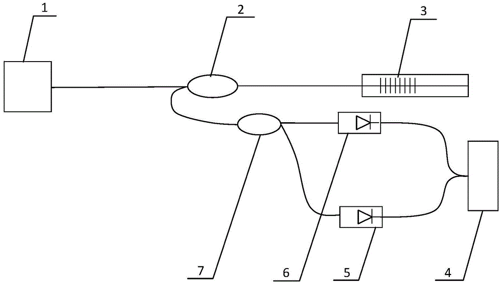
[0018] exist figure 1 Among them, the cladding fiber grating vibration sensor of the present embodiment consists of a semiconductor laser 1, a fiber circulator 2, a fiber grating sensor 3, an oscilloscope 4, a fiber core grating photodetector 5, a cladding grating photodetector 6, a fiber optic wave The multiplexer 7 is connected to form.

[0019] The semiconductor laser 1 is connected to the fiber circulator 2 through a single-mode fiber, and the laser light with a wavelength of 1520-1620nm generated by the semiconductor laser 1 is output to the fiber circulator 2 through the single-mode fiber, and the fiber circulator 2 is connected to the fiber grating sensor 3 and The optical fiber wavelength division multiplexer 7 is connected, the semiconductor laser 1 provides laser light for the fiber grating sensor 3 and the optical fiber wavelength division multiplexer 7, and the optical fiber wavelength division multiplexer 7 passes the single-mode optical fiber and the fiber core g...

Embodiment 2

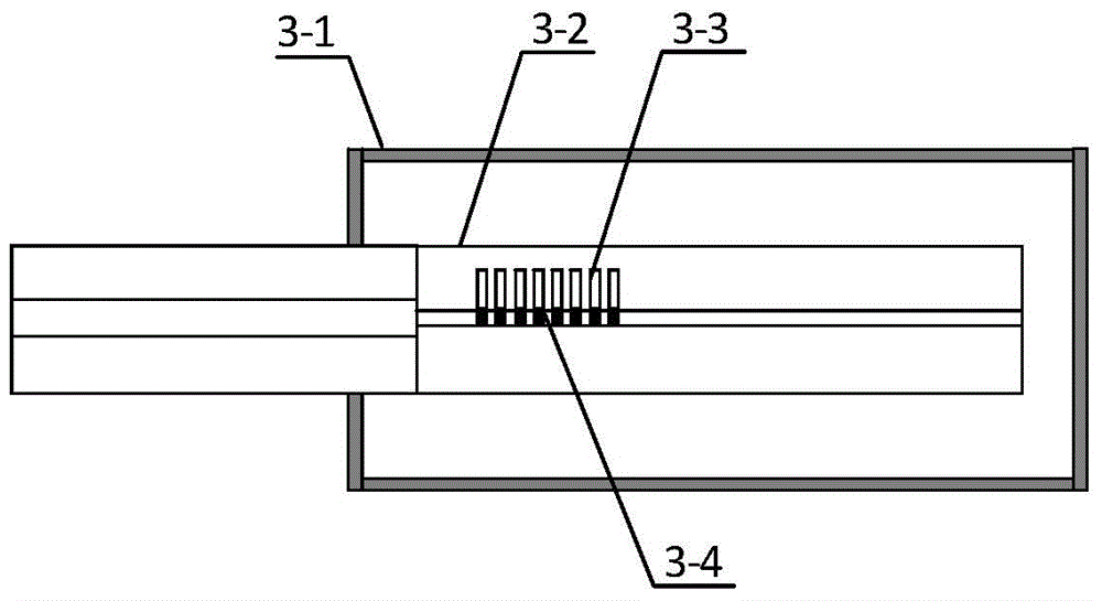
[0022] In this embodiment, the end of the single-mode optical fiber is fused with a thin-core optical fiber 3-2, a core grating 3-4 is written on the core of the thin-core optical fiber 3-2, and a cladding grating 3-4 is written on the fiber cladding. 3. The wavelength of the core grating 3-4 is 1520nm, the wavelength of the cladding grating 3-3 is 1512nm, the length of the cladding grating 3-3 is equal to the length of the fiber core grating 3-4, and the cladding grating 3-3 and The fiber core gratings 3-4 are arranged in parallel at the same axial length position. Other components and the coupling relationship of the components are the same as in Embodiment 1.

Embodiment 3

[0024] In this embodiment, the end of the single-mode optical fiber is fused with a thin-core optical fiber 3-2, the core of the thin-core optical fiber 3-2 is engraved with a core grating 3-4, and the fiber cladding is engraved with a cladding grating 3 -3, the cladding grating 3-3 is engraved on the fiber cladding, the wavelength of the core grating 3-4 is 1620nm, the wavelength of the cladding grating 3-3 is 1612nm, the length of the cladding grating 3-3 is the same as that of the core grating 3-4 are equal in length, and the cladding grating 3-3 and the fiber core grating 3-4 are arranged in parallel at the same axial length position. Other components and the coupling relationship of the components are the same as in Embodiment 1.


PUM


Abstract

The invention discloses a cladded optical fiber grating vibration sensor. A semiconductor laser is connected with an optical fiber circulator by single-mode optical fibers; the optical fiber circulator is connected with an optical fiber grating sensor and an optical fiber wavelength division multiplexer by the single-mode optical fibers; the optical fiber wavelength division multiplexer is connected with a cladded grating photoelectric detector and a fiber core grating photoelectric detector by the single-mode optical fibers; the cladded grating photoelectric detector and the fiber core grating photoelectric detector are connected with an oscilloscope by coaxial cables; a fiber core gratings is written on thin-core optical fibers; cladded gratings are written on optical fiber claddings. During shock detection of a building, laser emitted by the semiconductor laser is transmitted to the fiber core gratings and the cladded gratings through the optical fiber circulator, vibration of a to-be-detected vibrating body leads to changes of cladding energy distribution reflected by the cladded gratings and changes the energy which enters the single-mode optical fibers in a coupled manner, so that information of vibration direction is obtained, structural deformation of civil engineering such as bridges, tunnels and dams can be detected in real time, and interior structure of earth and earthquake wave propagation characteristics can be researched in order to predict impending earthquake.

Description

technical field [0001] The invention belongs to the technical field of sensors, and in particular relates to a fiber grating vibration sensor. Background technique [0002] As a new type of optical passive device, the fiber grating acceleration sensor has many advantages that electromagnetic acceleration sensors cannot match, such as high sensitivity, wide dynamic range, no electromagnetic interference, corrosion resistance, small transmission loss, high reliability, and small size. It has the characteristics of small size and light weight, and has the characteristics that the sensing signal is not affected by factors such as light source fluctuation and optical path loss, strong anti-interference ability, simple structure of the sensing probe, and easy to use wavelength division multiplexing technology to form distributed measurement. Therefore, the fiber grating acceleration sensor has become a new research and development direction. Optical fiber detectors have expanded ...

Claims


Application Information

Patent Timeline
Patent Type & Authority Applications(China)
IPC IPC(8): G01H9/00
Inventor 乔学光荣强周包维佳
Owner NORTHWEST UNIV(CN)
Why Eureka
Try Eureka