Method for measuring liquid surface tension by using transparent glass tube with scale marks

A liquid surface tension, transparent glass tube technology, applied in surface tension analysis and other directions, can solve the problems of difficulty, inaccurate measurement of liquid column height, and low measurement accuracy, and achieve clear surface phenomena, low measurement costs, and simple methods. Effect

Inactive Publication Date: 2015-03-04
SICHUAN UNIV
View PDF6 Cites 5 Cited by
  • Summary
  • Abstract
  • Description
  • Claims
  • Application Information

AI Technical Summary

Problems solved by technology

[0002] Common methods for measuring the surface tension coefficient of liquids are: maximum bubble pressure method, capillary method, pull-off method, etc. The measurement method is either complicated, such as the maximum bubble pressure method, pull-off method; or the measurement accuracy is not high, although the capillary method is simple , but the liquid surface is curved, and the height of the liquid column is not accurate enough. Since the liquid surface outside the capillary also rises along the tube wall outside the capillary, it is difficult to determine the coordinate value of the horizontal position of the liquid surface, which leads to the determination of the inside of the capillary. The height difference of the liquid column is more difficult

Method used


Image

  • Method for measuring liquid surface tension by using transparent glass tube with scale marks
  • Method for measuring liquid surface tension by using transparent glass tube with scale marks
  • Method for measuring liquid surface tension by using transparent glass tube with scale marks

Examples


Embodiment Construction

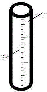
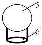
[0008] A transparent glass tube 1, the tube wall is thicker than 2 mm, it is recommended to be 2-5 mm, and there is a millimeter scale 2 on the outside of the transparent glass tube 1 along the axis direction (length direction) of the transparent glass tube 1 , the 0 scale line of the millimeter scale 2 is located at one end of the transparent glass tube 1, that is, the 0 scale line of the millimeter scale 2 is flush with the plane of one end of the transparent glass tube 1; The structure of the earball is the same, and it is composed of the airbag 5 and the airbag port 6, but the outer diameter of the airbag port 6 of the earwashing ball is basically the same as that of the transparent glass tube 1. Through the elasticity of the earwashing ball, the airbag port 6 is tightly covered with the transparent glass tube 1 Seal one end of the transparent glass tube 1 at the end where the 0 scale of the millimeter scale 2 is located, and extend the other end of the transparent glass tu...


PUM

PropertyMeasurementUnit
thicknessaaaaaaaaaa

Abstract

The invention discloses a method for measuring liquid surface tension by using a transparent glass tube with scale marks, and relates to measurement of physical parameters. According to the technical scheme, the method comprises the following steps: arranging a millimeter graduated scale on the outer side of the transparent glass tube, wherein the scale mark 0 of the millimeter graduated scale is positioned at a tube opening in one end of the transparent glass tube; mounting a rubber suction bulb which consists of an airbag and an airbag opening, tightly arranging the airbag opening at one end, at which the scale mark 0 of the millimeter graduated scale of the transparent glass tube is positioned, in a sleeving manner; compressing the airbag of the rubber suction bulb, sucking part of liquid into the transparent glass tube to form a liquid column, and vertically fixing the transparent glass tube on a bracket; removing the rubber suction bulb at the lower end of the transparent glass tube, so that a liquid column in the transparent glass tube moves downwards; stretching the open end of a liquid delivery tube into the liquid column in the transparent glass tube, slowly injecting the liquid into the transparent glass tube till the height of the liquid column does not rise any more, and recording the height h, wherein the surface tension coefficient sigma of the liquid is equal to d*h*rho*g/4. The method has the beneficial effect that the change of the surface tension inside the glass tube and at the tube opening can be clearly observed.

Description

technical field [0001] The invention relates to the measurement of physical parameters, especially the measurement of the surface tension coefficient of liquids. Background technique [0002] Common methods for measuring the surface tension coefficient of liquids are: maximum bubble pressure method, capillary method, pull-off method, etc. The measurement methods are either relatively complicated, such as the maximum bubble pressure method, pull-off method; or the measurement accuracy is not high, although the capillary method is simple , but the liquid surface is curved, and the height of the liquid column is not accurate enough. Since the liquid surface outside the capillary also rises along the tube wall outside the capillary, it is difficult to determine the coordinate value of the horizontal position of the liquid surface, which leads to the determination of the inside of the capillary. The height difference of the liquid column is more difficult. Contents of the inven...

Claims


Application Information

Patent Timeline
Patent Type & Authority Applications(China)
IPC IPC(8): G01N13/02
Inventor 李娟胡再国饶大庆朱俊何原雍志华罗明蓉穆万军邹旭敏王维果梁雅庭程艳刘石丹于白茹李伟梁小冲李紫源田野中
Owner SICHUAN UNIV
Why Eureka
Try Eureka