Split conductive wire clamp metal ware and branch wire clamps thereof

A technology for splitting wires and wire clip fittings, used in conductive connections, multi-conductor connectors, clamping/spring connections, etc., can solve the problem of being located on the outside of the branch clip, and achieve simple structure, convenient installation and use, and anti-corona performance. Good results

Active Publication Date: 2015-03-04
PINGGAO GRP +1
View PDF6 Cites 1 Cited by
  • Summary
  • Abstract
  • Description
  • Claims
  • Application Information

AI Technical Summary

Problems solved by technology

[0005] The present invention provides a branch line clamp for split wire clamp fittings to solve the problem that in the prior art, the compression block of each branch line clamp is arranged outside the corresponding branch line clamp, so that the seam between the compression block and the finger-shaped support body is located on the branch line Technical issues on the outside of the clip

Method used


Image

  • Split conductive wire clamp metal ware and branch wire clamps thereof
  • Split conductive wire clamp metal ware and branch wire clamps thereof
  • Split conductive wire clamp metal ware and branch wire clamps thereof

Examples


Embodiment Construction

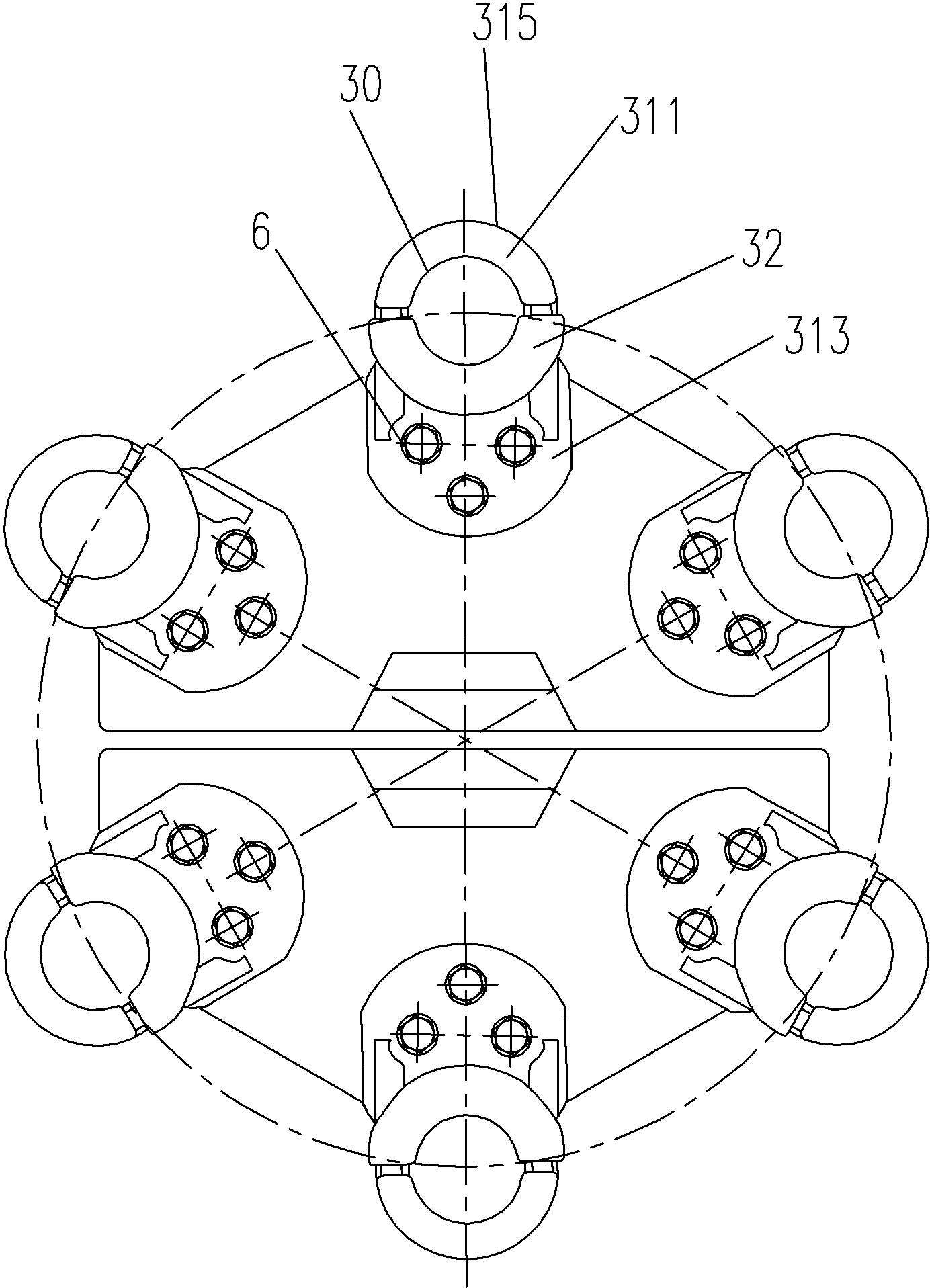
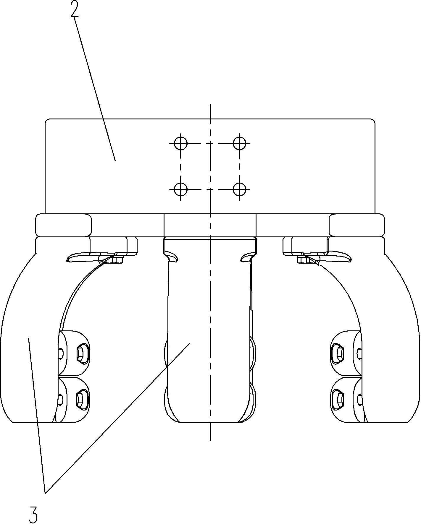
[0024] Such as figure 1 As shown, a kind of embodiment of the split wire clamp hardware, the wire clamp hardware in this embodiment includes a busbar clamp 2, the busbar clamp 2 is provided with a busbar hole for clamping the busbar, and the busbar hole along the busbar clamp 2 One end extending in the axial direction is fixed with six branch line clamps 3 uniformly distributed around the busbar hole circumferentially, and each branch line clamp 3 has a branch line hole 30 arranged coaxially and parallel to the busbar hole for clamping branch lines.

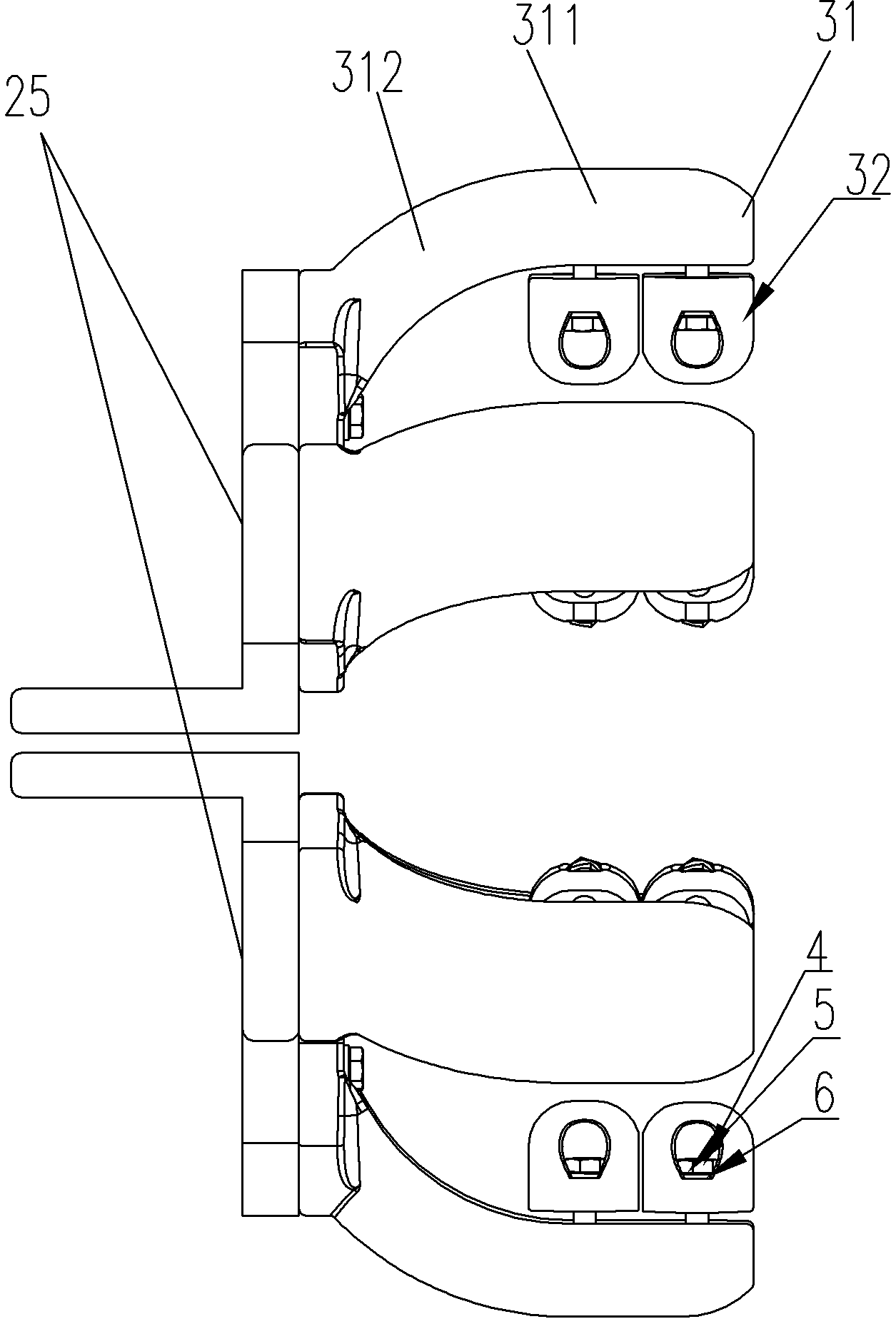
[0025] The bus bar clamp 2 in this embodiment includes pipe mother holding clips 25 that are assembled together correspondingly, and the pipe mother holding clips 25 are L-shaped.

[0026] In this embodiment, there are six branch wire clips 3 evenly distributed around the circumference of the busbar hole, three of which are fixed on the installation baffle of a tube mother holding clip through connecting screws 6, and the other t...


PUM


Abstract

The invention provides a split conductive wire clamp metal ware and branch wire clamps thereof. The wire clamp metal ware comprises a bus clamp. One end, which axially extends along the bus hole, of the bus clamp is fixedly provided with the branch wire clamps. Each branch wire clamp comprises a finger-shaped supporting body and a compressing block. The finger-shaped supporting body is provided with an axial installing segment which axially extends along the branch wire hole and a radial installing segment which radially extends along the branch wire hole and is integrally arranged or fixedly arranged on the bus clamp in a split way. The compressing block is arranged at the internal side of a bending structure formed by the axial installing segment and the radial installing segment on the finger-shaped supporting body and fixedly arranged on the axial installing segment. The opposite side surfaces of the radial installing segment and the compressing block are provided with branch wire grooves forming the branch wire holes. The axial installing segment and the radial installing segment of the finger-shaped supporting body are connected via an arc transition connecting segment in a transition way. The compressing blocks of all the branch wire clamps are arranged at the internal sides, which orient the central axis of the bus hole, of the corresponding branch wire clamps. The wire clamp metal ware is simple in structure, convenient to install and use and great in anti-corona performance.

Description

technical field [0001] The invention relates to a split wire clip fitting and a branch clip thereof. Background technique [0002] At present, most of the equipment clamps for AC substations put into operation in my country are two-split and four-split wire equipment clamps, while the rated capacity and rated current delivered by DC UHV converter stations are relatively large, and six-split wire equipment clamps are required to meet the requirements. Requirements for UHV DC converter stations. [0003] In the Chinese utility model patent specification whose authorized announcement number is CN203039122U, a wire connection fitting is disclosed, which is used to conduct the corresponding conduction between the pipe busbar and each branch wire. For the busbar hole of the busbar, four branch clamps uniformly distributed around the circumference are arranged on the end of the busbar clamp extending along the axial direction of the busbar hole, and each branch clamp is provide...

Claims


Application Information

Patent Timeline
Patent Type & Authority Applications(China)
IPC IPC(8): H01R11/01
CPCH01R4/46H01R11/05
Inventor 张爱芳常林晶李俊辉王品珍雷咸伦王刚
Owner PINGGAO GRP
Why Eureka
Try Eureka