A terminal mating connector

A terminal matching and connector technology, applied in the direction of connection, connecting device parts, electrical components, etc., can solve problems such as impedance mismatch, signal interference, cable aging, etc., to ensure the quality of signal transmission and eliminate interference.

Active Publication Date: 2017-08-25
SICHUAN HUAFENG ENTERPRISE GRP
View PDF6 Cites 0 Cited by
  • Summary
  • Abstract
  • Description
  • Claims
  • Application Information

AI Technical Summary

Problems solved by technology

[0002] During communication, there are two types of signals that cause signal reflections: impedance discontinuity and impedance mismatch
In order to eliminate the influence of reflection and crosstalk on the transmission line, the usual practice is to load a terminal resistor with the same size as the characteristic impedance of the cable on the cable behind the plug. The problems in doing so are as follows: (1) During use In the aging of the cable, the energy consumption of the resistor will also increase, which will inevitably lead to a mismatch between the terminal resistance and the characteristic impedance of the cable; (2) This structure itself increases the weight and volume of the connector. In the development of connector miniaturization, It must be eliminated; (3) When the plug and the socket are not connected, the plug is equivalent to an antenna, which will inevitably introduce signal interference, etc.; (4) This structure is not easy to handle in harsh environments

Method used


Image

  • A terminal mating connector
  • A terminal mating connector
  • A terminal mating connector

Examples


Embodiment Construction

[0026] In order to make the purpose, technical solution and advantages of the present application clearer, the present application will be further described in detail below in conjunction with the accompanying drawings and specific embodiments.

[0027] For simplicity, some technical features known to those skilled in the art are omitted from the following description.

[0028] The present application provides a terminal mating connector satisfying the miniaturization of the connector.

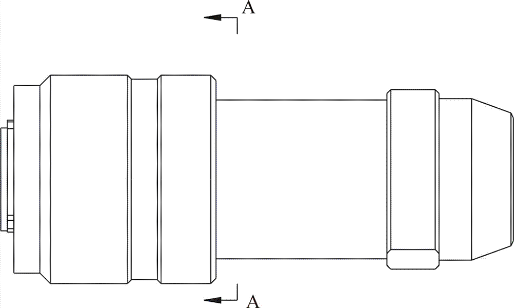
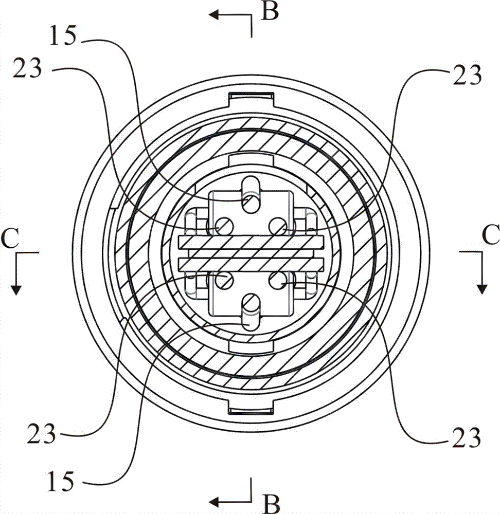
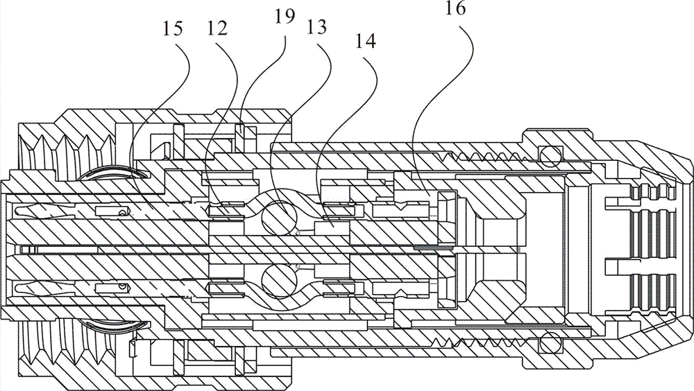
[0029] Such as Figure 1-Figure 5 As shown, the above-mentioned terminal mating connector includes a shell.

[0030] The shell may include a connecting ring 1 , a head shell 2 and a knurled nut 3 ;

[0031] The connecting ring 1 can be clamped on the outside of the head housing 2 . Plastic teeth 17 can be arranged in the cavity formed after the coupling ring 1 and the head housing 2 are matched; stop washers 18 and retaining rings 19 can be arranged on both sides of the plastic teeth 17 res...


PUM


Abstract

The invention discloses a terminal matching connector, including a shell, a first contact pin assembly and a first solder cup assembly matched with the fist contact pin assembly, wherein a ground lug is arranged in the shell, a printed board is arranged on at least one side of the ground lug, at least one resistor is arranged on the printed board, the first contact pin assembly is fixed in the shell through a front mounting plate, the first solder cup assembly is fixed on the shell through a rear mounting plate, the first contact pin assembly and the first solder cup assembly are electrically connected to the printed board, the first contact pin assembly comprises at least one differential pair contact element, and two ends of the resistor are respectively electrically connected to the printed board by the differential pair contact element. The terminal matching connector eliminates reflection and crosstalk influence on a transmission line; as both the printed board and the differential pair can be miniaturized and microminiaturized, in combination of an existing surface mounting technology, the miniaturization and microminiaturization requirements of the connector can be met; due to the arranged of a packaging sleeve and a shielding ring, interference that may be brought in from the outside can be further eliminated, and the signal transmission quality is ensured.

Description

technical field [0001] The invention belongs to the technical field of connectors, and relates to a connector with a terminal matching function. Background technique [0002] During communication, there are two types of signals that cause signal reflections: impedance discontinuities and impedance mismatches. In order to eliminate the influence of reflection and crosstalk on the transmission line, the usual practice is to load a terminal resistor with the same size as the characteristic impedance of the cable on the cable behind the plug. The problems in doing so are as follows: (1) During use In the aging of the cable, the energy consumption of the resistor will also increase, which will inevitably lead to a mismatch between the terminal resistance and the characteristic impedance of the cable; (2) This structure itself increases the weight and volume of the connector. In the development of connector miniaturization, It must be eliminated; (3) When the plug and the socket ...

Claims


Application Information

Patent Timeline
Patent Type & Authority Patents(China)
IPC IPC(8): H01R13/6594H01R13/6591
CPCH01R13/6591H01R13/6594
Inventor 刘俊庞斌刘小凤
Owner SICHUAN HUAFENG ENTERPRISE GRP
Why Eureka
Try Eureka