Reactive continuous compensation control method for thyristor switched filter

A thyristor switching, compensation control technology, applied in reactive power compensation, reactive power adjustment/elimination/compensation, harmonic reduction devices, etc., can solve problems such as reactive power overcompensation, reactive power compensation discontinuity, etc. Efficient, effective reactive power compensation and harmonic suppression, the effect of prolonging the service life

Active Publication Date: 2015-03-04
北京锌科能源技术有限公司
View PDF4 Cites 7 Cited by
  • Summary
  • Abstract
  • Description
  • Claims
  • Application Information

AI Technical Summary

Problems solved by technology

[0004] The purpose of the present invention is to solve the problem of discontinuous reactive power compensation of the thyristor switching filter in the prior art and easily cause reactive power overcompensation, and to provide a reactive power continuous compensation control method for the thyristor switching filter

Method used


Image

  • Reactive continuous compensation control method for thyristor switched filter
  • Reactive continuous compensation control method for thyristor switched filter
  • Reactive continuous compensation control method for thyristor switched filter

Examples


specific Embodiment approach 1

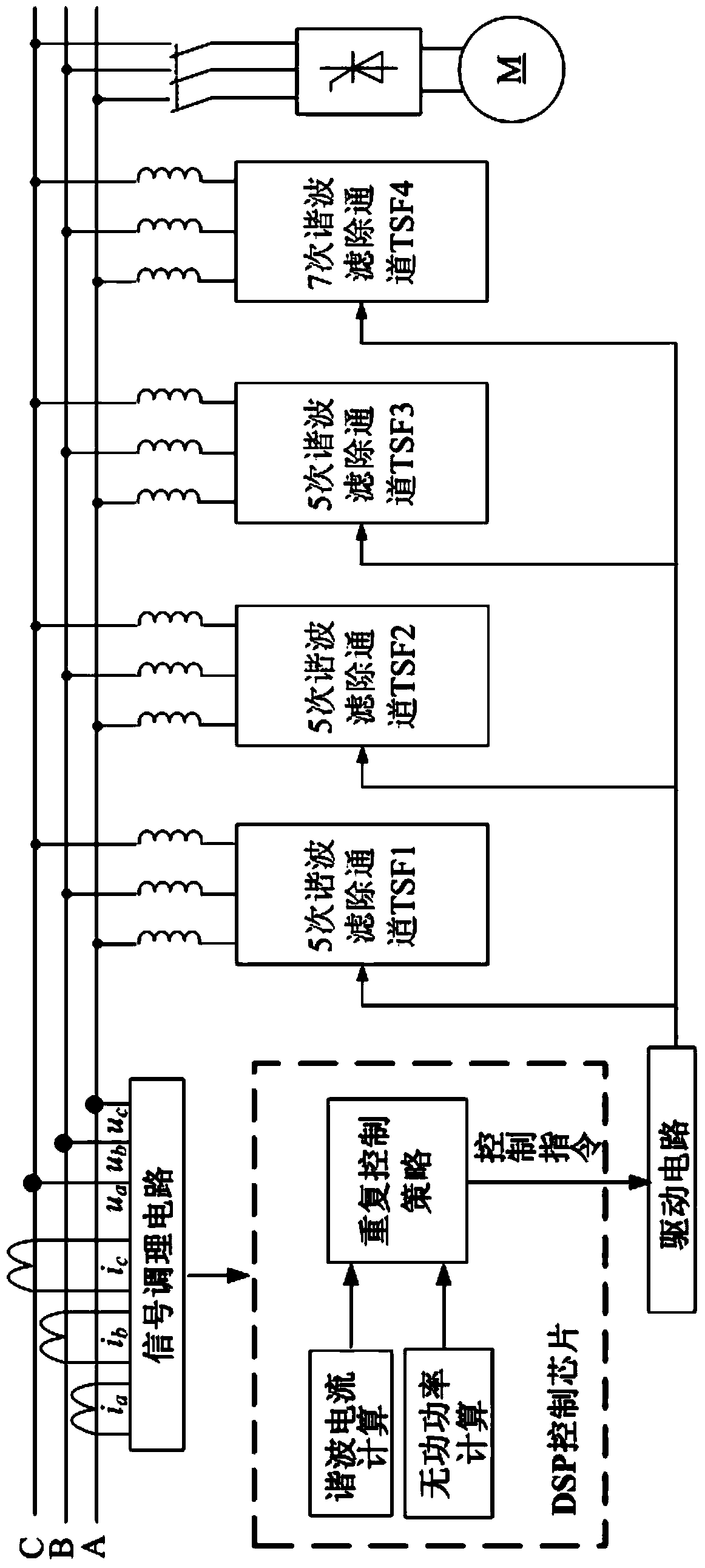
[0032] Specific implementation mode one: the following combination Figure 1 to Figure 18 Describe this embodiment, the reactive power continuous compensation control method of the thyristor switching filter described in this embodiment, this method uses the switching of the thyristor switching filter to perform reactive power compensation control on the system, and the system is provided with three 5th harmonics Filter channels TSF1, TSF2, TSF3 and a 7th harmonic filter channel TSF4.

[0033] The method includes the following steps:

[0034] Step 1, the three-phase voltage signal u on the load side of the power grid where the thyristor switching filter is located a , u b , u c and the three-phase current signal i a , i b , i c to sample;

[0035] Step 2. The three-phase voltage signal u obtained in step 1 is processed by the signal conditioning circuit a , u b , uc and the three-phase current signal i a , i b , i c Process and send the processed signal to the DSP ...

specific Embodiment approach 2

[0043] Specific implementation mode 2: This implementation mode further explains the implementation mode 1, and obtains the harmonic component i in step 3 ah , i bh , i ch The process is:

[0044] Step 31, the three-phase current signal i a , i b , i c by formula

[0045] i α i β = C 3 / 2 i a i b i c = 2 3 ...

specific Embodiment approach 3

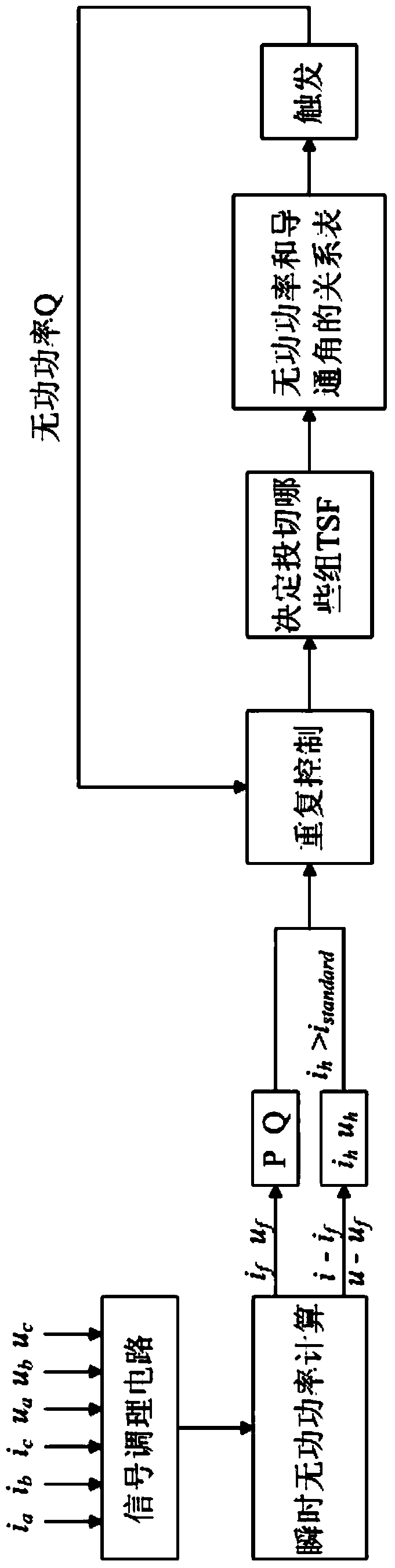
[0061] Specific implementation mode three: This implementation mode further explains implementation mode one. The establishment process of the conduction angle and reactive power compensation capacity database in step four is: change the size of the thyristor conduction angle δ in the thyristor switching filter, and collect different Thyristor switching filter reactance X at thyristor conduction angle δ L , load power factor angle and according to the formula Obtain the corresponding reactive power Q, and establish a database of the corresponding relationship between the conduction angle δ of the thyristor and the reactive power Q.

[0062] According to the structure diagram of the filter system, according to Kirchhoff's law, write the circuit equation and solve it to get:

[0063] Formula one:

[0064]

[0065] Formula two:

[0066]

[0067] In the above two formulas, I m is the peak current of the fundamental wave of the filter, ω is the angular frequency of the...


PUM


Abstract

The invention discloses a reactive continuous compensation control method for a thyristor switched filter and belongs to the technical field of application combining power electronics and electric energy quality control, so as to solve the problem that reactive over compensation is likely to happen due to discontinuous reactive compensation of the thyristor switched filter in the prior art. The method of the invention adopts switching of the thyristor switched filter to carry out reactive compensation control on the system, and the system is provided with three fifth harmonic filtering channels TSF1, TFS2 and TSF3 and a seventh harmonic filtering channel TSF4. The method comprises the following steps: three phases of voltage signals ua, ub and uc and three phases of current signals ia, ib and ic are acquired; after the signals are conditioned, the signals are sent to a DSP control chip; in the DSP control chip, seventh harmonic current and fifth harmonic current are acquired; and the switching state of each harmonic filtering channel is determined.

Description

technical field [0001] The invention relates to a reactive continuous thyristor switched filter (TSF, thyristor switched filter) control technology, which belongs to the application technical field of combining power electronics and power quality control. Background technique [0002] Thyristor switching filter is a power electronic device used to dynamically suppress harmonics and compensate reactive power. It can perform real-time monitoring and dynamic compensation for impact loads and time-varying loads, filter out harmonics, and maintain the best power factor at any time, which is of great significance for reducing power grid losses, saving electric energy, and improving power quality. [0003] The conventional thyristor switching filter adopts the "zero-crossing switching" method, that is, it is switched on when the voltage of the parallel thyristors crosses zero, and it is automatically cut off when the current is zero. Although this method can accurately control the...

Claims


Application Information

Patent Timeline
Patent Type & Authority Applications(China)
IPC IPC(8): H02J3/18H02J3/01
CPCH02J3/01H02J3/1864Y02E40/30Y02E40/40
Inventor 王立国张海聪杨喆徐殿国于健雄李振宇高寒刘悦李雪云栾添瑞张淋
Owner 北京锌科能源技术有限公司
Why Eureka
Try Eureka