
Peak clipping pulse wave modulation system based on two-stage low-pass filter and amplification treatment

A low-pass filter and pulse modulation technology, applied in the electronic field, can solve the problem of low power and achieve the effect of preventing voltage instability

Inactive Publication Date: 2015-03-04
CHENGDU COPOO TECH
View PDF0 Cites 2 Cited by
  • Summary
  • Abstract
  • Description
  • Claims
  • Application Information

AI Technical Summary

Problems solved by technology

[0003] The purpose of the present invention is to overcome the defect that the output power of the traditional pulse wave circuit is not high enough to meet people's increasing electrical needs, and to provide a peak-shaving pulse wave modulation system based on two-stage low-pass filter amplification processing

Method used


Image

  • Peak clipping pulse wave modulation system based on two-stage low-pass filter and amplification treatment

Examples


Embodiment

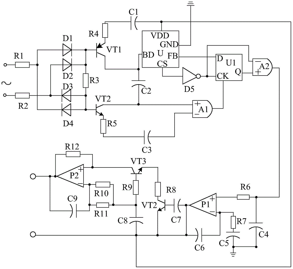
[0014] Such as figure 1 As shown, the peak clipping pulse modulation system based on the two-stage low-pass filter amplification processing of the present invention mainly includes a peak clipping circuit and a pulse modulation circuit connected to the output end of the peak clipping circuit. In order to realize the purpose of the present invention, a two-stage low-pass filter amplifier circuit is also provided at the output end of the pulse wave modulation circuit.

[0015] Among them, the two-stage low-pass filter amplifying circuit is composed of amplifier P1, amplifier P2, transistor VT2, transistor VT3, the positive pole is connected to the pulse wave modulation circuit, the negative pole is grounded capacitor C4, one end is connected to the positive phase input end of the amplifier P1, The other end of the resistor R6 is connected to the positive pole of the capacitor C4, the positive pole is connected to the inverting input terminal of the amplifier P1 after passing thr...


PUM


Abstract

The invention discloses a peak clipping pulse wave modulation system based on two-stage low-pass filter and amplification treatment. The peak clipping pulse wave modulation system based on two-stage low-pass filter and amplification treatment mainly comprises a peak clipping circuit and a pulse wave modulation circuit connected with the output end of the peak clipping circuit. The peaking clipping pulse wave modulation system based on the two-stage low-pass filter and amplification treatment is characterized in that a two-stage low-pass filter and amplification circuit is further arranged at the output end of the pulse wave modulation circuit, wherein the two-stage low-pass filter and amplification circuit consists of an amplifier P1, an amplifier P2, a triode VT2, a triode VT3, a capacitor C4, a resistor R6, a capacitor C5, a capacitor C6, and the like, wherein the positive electrode of the capacitor C4 is connected with the pulse wave modulation circuit, the negative electrode of the capacitor C4 is grounded; one end of the resistor R6 is connected with the positive phase input end of the amplifier 91 and the other end of the resistor R6 is connected with the positive electrode of the capacitor C4; the positive electrode of the capacitor C5 is connected with an inverted phase input end of the amplifier P1 after passing through a resistor R7, and the negative electrode of the capacitor C5 is connected with the negative electrode of the capacitor C4; and the capacitor C6 is connected in series between the output end and the inverted phase input end of the amplifier P1. By adopting the two-stage low-pass filter and amplification circuit, the peak clipping pulse wave modulation system disclosed by the invention can be used for amplifying the output power of the modulation system, so that the modulation system can meet the needs of simultaneously using more electrical appliances.

Description

technical field [0001] The invention relates to the field of electronics, in particular to a peak-shaving pulse wave modulation system based on two-stage low-pass filter amplification processing. Background technique [0002] The application of electric energy is becoming more and more popular in social production and human life, and electrical appliances that meet various requirements are also emerging. In daily life, people usually use pulse modulation circuits to power electrical appliances to meet people's use of electrical appliances. However, in actual use, the output power of the pulse modulation circuit is not high, which cannot meet people's increasing electrical needs. Contents of the invention [0003] The purpose of the present invention is to overcome the defect that the output power of the traditional pulse wave circuit is not high enough to meet people's increasing electrical needs, and to provide a peak-shaving pulse wave modulation system based on two-stag...

Claims


Application Information

Patent Timeline
Patent Type & Authority Applications(China)
IPC IPC(8): H02M1/08
CPCH02M1/00
Inventor 车容俊高小英
Owner CHENGDU COPOO TECH
Learn More