Device and method for determining relative displacements of body parts or body areas

A body area and body part technology, applied in the direction of using optical devices to transmit sensing components, applications, using light for diagnosis, etc., can solve the problems of high equipment, inaccurately inferring the actual displacement of the spine, cost, etc.

Inactive Publication Date: 2015-03-04
OTTO BOCK HEALTHCARE IP GMBH & CO KG
View PDF5 Cites 0 Cited by
  • Summary
  • Abstract
  • Description
  • Claims
  • Application Information

AI Technical Summary

Problems solved by technology

[0003] The last-mentioned methods require high equipment expenditure, are generally applicable only in special environmental situations and cannot or only inaccurately determine the actual rotation within the spine or the actual displacement of the individual body regions or body parts

Method used


Image

  • Device and method for determining relative displacements of body parts or body areas
  • Device and method for determining relative displacements of body parts or body areas
  • Device and method for determining relative displacements of body parts or body areas

Examples


Embodiment Construction

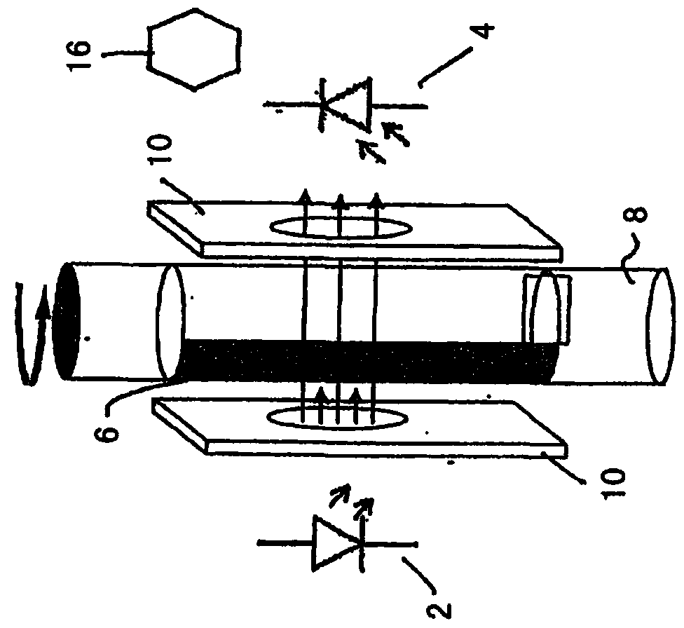
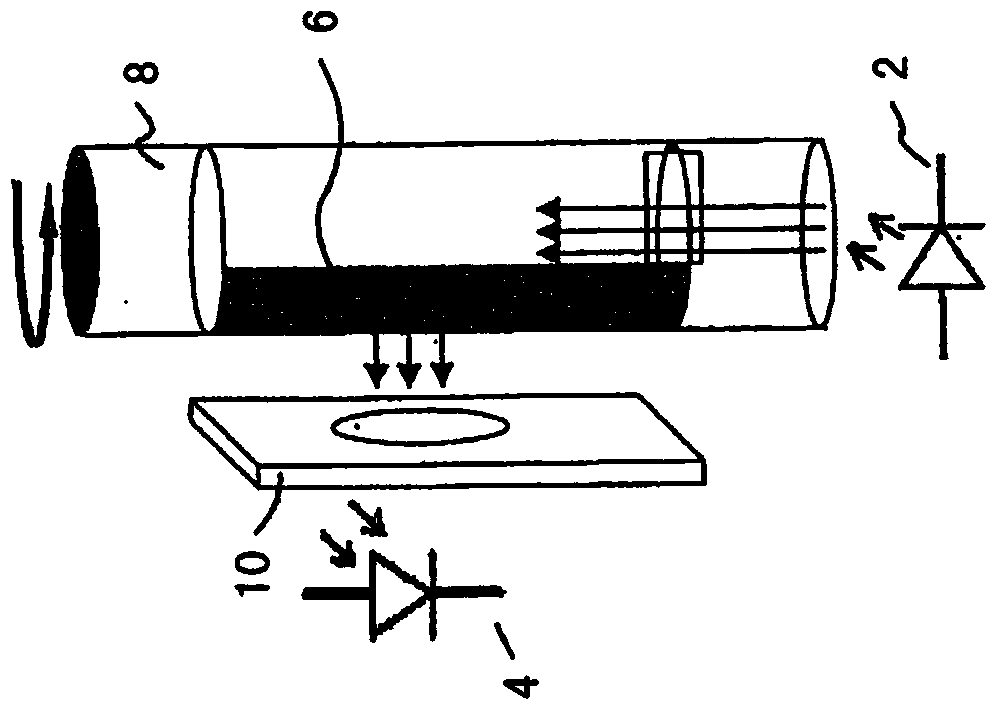
[0029] exist figure 1 In a schematic diagram, a device for determining the relative displacement of body parts and body regions is shown, which has a light source as transmitting device 2 which sends light through two aperture plates in the direction of a sensor 4 . The transmitting device 2 is designed as a light-emitting diode (LED). The sensor 4 is designed as a photodiode. A shielding device 6 is arranged between the transmitting device 2 and the sensor 4 , said shielding device being fastened to an elongated base body 8 . While the screening device 6 in the illustrated embodiment is applied as a light-tight coating on the outside, alternative screening devices are possible. For example, the base body 8 of a light-impermeable material with a flattened portion on one side of the periphery can be arranged so that by rotating the base body 8 about its longitudinal axis, the sensor 4 is loaded with different radiation intensities . The rotation of the base body 8 about thi...


PUM


Abstract

The invention relates to a device and a method for determining relative displacements of body parts or body areas, with a transmitter (2) and a sensor (4) associated with the transmitter (2), wherein at least one shadowing device (6), which is displaceable relative to the sensor (4) and/or the transmitter (2) and is fixed to at least one body part or body area, is arranged between the transmitter (2) and the sensor (4).

Description

technical field [0001] The invention relates to a device and a method for determining a relative displacement of a body part or body region, which have a transmitter and a sensor associated with the transmitter. The invention is particularly suitable for detecting spinal twisting or spinal rotation during motion. Background technique [0002] In addition to purely photographing with the aid of one or more cameras, methods are known in which markings are applied to the body surface of a person for detecting movement data and movement sequences. A camera is used to photograph the moving person, the markings being arranged at the joint points. The motion of the joints relative to each other is detected by a camera device and converted into a model in the computer and imaged on a display. From this model, relative movements of body parts or body regions relative to each other can be calculated, wherein the calculation is based on model assumptions. Therefore, the spine is mos...

Claims


Application Information

Patent Timeline
Patent Type & Authority Applications(China)
IPC IPC(8): G01D5/34
CPCG01D5/34A61B2090/3945A61B2090/3975A61B90/39A61B2090/3958A61B5/0059A61B5/05A61B5/1114A61B5/1127A61B2562/164
Inventor J·克鲁肯贝格T·冯马卡尔德
Owner OTTO BOCK HEALTHCARE IP GMBH & CO KG
Why Eureka
Try Eureka