Non-electric constant temperature foot bath

A foot bath and constant temperature technology, which is applied to bathtubs, showers, household appliances, etc., can solve the problems of inability to accurately control the flow of hot water, the inability to control the constant temperature of the foot bath area, and hidden dangers

Active Publication Date: 2016-08-31
杜志刚
View PDF5 Cites 0 Cited by
  • Summary
  • Abstract
  • Description
  • Claims
  • Application Information

AI Technical Summary

Problems solved by technology

[0002] At present, the constant temperature foot baths of the prior art are all heated by electricity, and they need to be connected to the power supply all the time, which is troublesome and has certain safety hazards. Chinese patent CN2014100526549 discloses a constant temperature foot bath without electricity, which is A high-temperature water storage area and a foot bath area are set in a basin, and the water storage area and the foot bath area are connected through a valve, and the speed of the high-temperature water in the water storage area flowing into the foot bath area is controlled by the valve to keep the temperature of the foot bath area constant, but in fact, there are many problems in this invention. The problem makes this invention difficult to realize. First, the water storage area and the foot bath area of ​​this invention are in the same basin, separated only by a baffle. During use, the high-temperature water in the water storage area will conduct heat through the baffle to make the temperature of the foot bath area rise rapidly. , so it is impossible to control the constant temperature of the footbath area; in addition, the valve is set on the inner layer of the basin bottom of the footbath area, and then the valve is opened to release hot water by pedaling. This method cannot precisely control the flow of hot water, so the footbath area cannot be controlled Constant temperature, at the same time, because the hot water released is directly on the soles of the feet, it is easy to burn the soles of the feet

Method used


Image

  • Non-electric constant temperature foot bath
  • Non-electric constant temperature foot bath
  • Non-electric constant temperature foot bath

Examples


Embodiment Construction

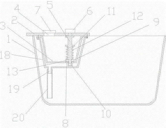
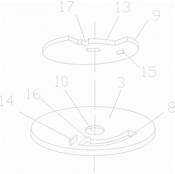
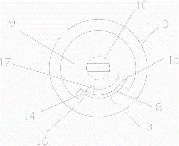
[0016] Such as figure 1 As shown, the non-electric constant temperature foot bath of the present invention includes a basin body 1 and a heat preservation cover 2, a box body 3 is fixed below the heat preservation cover 2, and a water injection device for filling water into the box body 3 is arranged on the heat preservation cover 2. There is a water outlet 4 and a valve for discharging water at the bottom of the box body 3, and the top end of the valve stem 5 extends out of the cover plate 2 and is fixedly connected with the knob 6 positioned above the cover plate 2, as figure 1 , figure 2 As shown, the above-mentioned valve includes a through hole 8 located at the bottom of the box body 3 for discharging water. The through hole 8 is covered with a valve plate 9 that can rotate relative to the through hole 8 and control the switch of the through hole 8. The valve plate 9 and the valve stem 5 The bottom end is slidingly connected, and there is a valve stem 5 positioning hol...


PUM


Abstract

The invention discloses a non-electrical constant-temperature foot tub, and the foot tub comprises a tub body and a thermal insulation cover plate, wherein a box body is fixed below the thermal insulation cover plate, a water filling nozzle capable of injecting water into the box body is arranged on the thermal insulation cover plate, a valve for releasing water is arranged at the bottom of the box body, and the valve rod top of the valve is extended out of the cover plate and fixedly connected with a rotary knob on the cover plate. In use, hot water appropriate for foot-soaking temperature is poured into the tub body, high-temperature water is injected into the box body through the water filling nozzle on the thermal insulation cover plate, the rotary knob on the cover plate is rotated to open the valve at the bottom of the box body such that the high-temperature water in the box body can slowly flow into the tub body and mix with the hot water therein, when the dissipated heat of the hot water in the tub body and the supplementary heat from the high-temperature water reach a balance state, the hot water in the tub body can keep constant temperature, the water velocity of the valve is controlled by adjusting the rotating angle of the rotary knob, and the inflow velocity of the different high-temperature water can make the hot water in the tub body at different constant temperature.

Description

technical field [0001] The invention relates to a foot bath. Background technique [0002] At present, the constant temperature foot baths in the prior art are all heated by electricity, and they need to be connected to the power supply all the time, which is troublesome and has certain safety hazards. Chinese patent CN2014100526549 discloses a constant temperature foot bath that does not use electricity. It is A high-temperature water storage area and a foot bath area are set in a basin, and the water storage area and the foot bath area are connected through a valve, and the speed of the high-temperature water in the water storage area flowing into the foot bath area is controlled by the valve to keep the temperature of the foot bath area constant, but in fact, there are many problems in this invention. The problem makes this invention difficult to realize. First, the water storage area and the footbath area of ​​the invention are in the same basin, separated only by a baff...

Claims


Application Information

Patent Timeline
Patent Type & Authority Patents(China)
IPC IPC(8): A47K3/022
Inventor 杜志刚
Owner 杜志刚
Why Eureka
Try Eureka