
Air blowing clamp for numerical control machine tool

A technology of CNC machine tools and fixtures, applied in the field of tooling and fixtures, can solve the problems of reducing production efficiency, easy deviation of dimensions, and product quality, etc., and achieves the effect of reducing defective rate, ensuring accuracy, and improving stability.

Active Publication Date: 2015-03-11
安徽上禾阜机械配件有限公司
View PDF7 Cites 17 Cited by
  • Summary
  • Abstract
  • Description
  • Claims
  • Application Information

AI Technical Summary

Problems solved by technology

[0002] In the process of modern industrial production, fixtures have been widely used in the processing of CNC machine tools. When clamping the workpiece, if the fixture cannot fix the workpiece well, it will cause problems in the quality of the product and the size is easy to produce. Deviation, processing accuracy and precision cannot be well guaranteed, resulting in low production efficiency and workpiece product qualification rate. At the same time, a large amount of waste will be generated when the CNC machine tool is processed. If it is not cleaned in time, it will cause damage to the machine tool. damage, which greatly reduces production efficiency and is not conducive to production

Method used


Image

  • Air blowing clamp for numerical control machine tool
  • Air blowing clamp for numerical control machine tool

Examples


Embodiment Construction

[0013] The present invention is described below in conjunction with accompanying drawing.

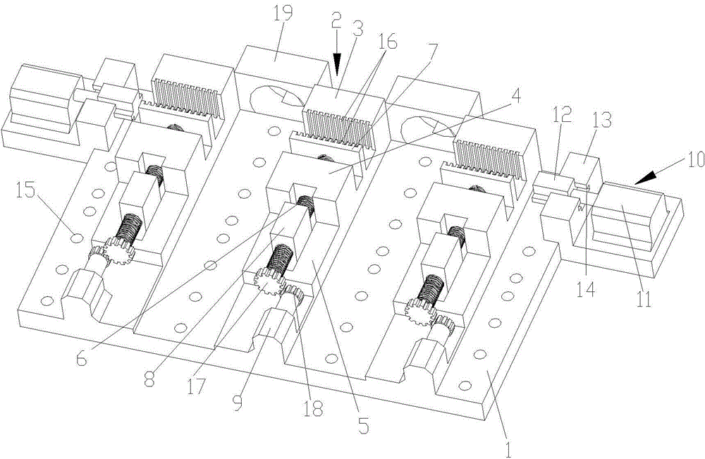
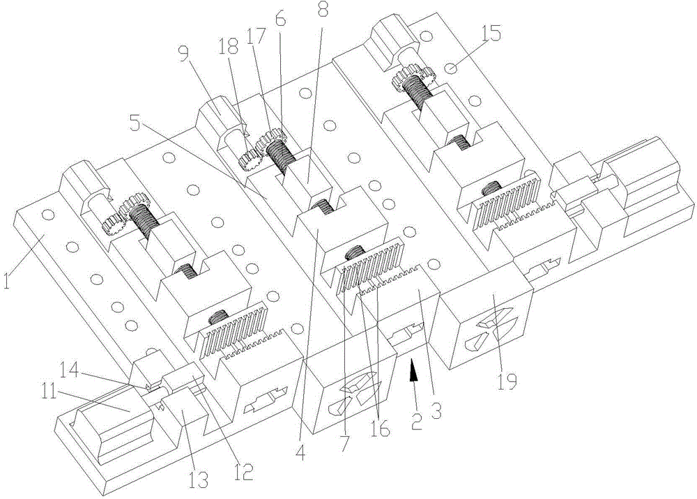
[0014] as attached figure 1 , 2 Shown is a blowing fixture for a CNC machine tool according to the present invention, including a base 1 and a processing station 2; the processing station 2 includes a fixed baffle 3, a support seat 4 and a moving groove 5; the fixed baffle 3 and the support seat 4 are provided with a clamping block 7 connected by a screw 6; one end of the screw 6 passes through the support seat 4 and is installed in the moving seat 8, and the first gear 17 is connected to the end extending out of the moving seat 8; The first gear 17 meshes with the second gear 18 arranged on the motor 9 on the base 1, and rotates the screw rod 6 through the rotation of the motor 9; 5; the processing station 2 is provided with three groups in parallel on the base 1, and a blowing device 19 is arranged between two; the base 1 is also provided with a top tightening structure 10 outside t...


PUM


Abstract

The invention discloses an air blowing clamp for a numerical control machine tool. The air blowing clamp comprises a pedestal and total three groups of processing workstations, wherein each processing workstation comprises a fixed baffle plate, a supporting seat and a moving groove; a clamping block connected by a screw rod is arranged between each of the fixed baffle plates and the corresponding supporting seat; one end of each of the screw rods penetrates through the supporting seat, and is installed in a moving seat; moreover, the end, stretching out of the moving seat, of each of the screw rods is connected with a first gear; the first gears are respectively engaged with second gears arranged on motors on the pedestal; moreover, the screw rods are driven to rotate through the rotation of the motors; the moving seats are respectively installed in the moving grooves, and can move in the moving grooves; the total three groups of processing workstations are arranged on the pedestal in parallel; an air blowing device is arranged between every two adjacent groups of processing workstations; the outer sides of the processing workstations on the pedestal are also respectively provided with a tightly-pushing structure. By applying the clamp, the stability of a product in processing is improved greatly, the precision of processing is guaranteed, the quality of the product is improved, and the defective rate is lowered.

Description

technical field [0001] The invention relates to a blowing fixture for a numerically controlled machine tool, belonging to the technical field of fixtures. Background technique [0002] In the process of modern industrial production, fixtures have been widely used in the processing of CNC machine tools. When clamping the workpiece, if the fixture cannot fix the workpiece well, it will cause problems in the quality of the product and the size is easy to produce. Deviation, processing accuracy and precision cannot be well guaranteed, resulting in low production efficiency and workpiece product qualification rate. At the same time, a large amount of waste will be generated when the CNC machine tool is processed. If it is not cleaned in time, it will cause damage to the machine tool. The damage greatly reduces the production efficiency and is not conducive to the progress of production. Contents of the invention [0003] In view of the above-mentioned technical problems, the p...

Claims


Application Information

Patent Timeline
Patent Type & Authority Applications(China)
IPC IPC(8): B23Q3/06B23Q3/08B23Q11/00
CPCB23Q3/061B23Q3/066B23Q3/08B23Q11/005B23Q2703/04
Inventor 顾卫建
Owner 安徽上禾阜机械配件有限公司
Learn More