
A multifunctional machine tool

A multifunctional machine tool and machine body technology, applied in the field of multifunctional machine tools, can solve the problems of inability to process workpieces, multiple positioning and processing of workpieces, and small tool magazine capacity, so as to achieve short auxiliary time, increase tool change space, and improve processing efficiency. and the effect of machining accuracy

Inactive Publication Date: 2017-03-15
SHANDONG NEW ANKAI KITCO SCI&TECH
View PDF5 Cites 0 Cited by
  • Summary
  • Abstract
  • Description
  • Claims
  • Application Information

AI Technical Summary

Problems solved by technology

[0002] Existing multi-functional machine tool changes are all done inside the machine body. When the tool is changed, the workpiece stops processing. Waiting for the spindle to lift and change the tool affects the processing efficiency of the workpiece. In addition, the internal space of the machine body is small and the capacity of the tool magazine is small, so it is impossible to process the workpiece. Too many processes are processed, resulting in low machining efficiency of the machine tool, small process range, and complex workpieces that require multiple positioning processes, which not only affects the machining accuracy, but also most of the existing machine tools process the workpiece with the spindle extending out of the spindle box. Fixed, because the strength decreases after the spindle is extended, it is easy to vibrate during the machining process, which affects the machining accuracy of the workpiece

Method used


Image

  • A multifunctional machine tool
  • A multifunctional machine tool
  • A multifunctional machine tool

Examples


Embodiment Construction

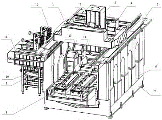
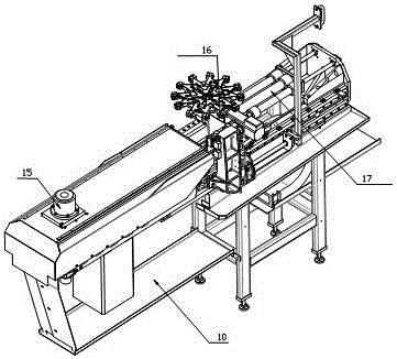
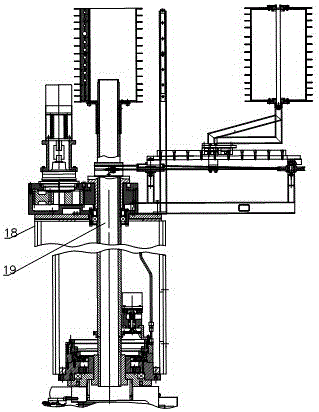
[0023] Accompanying drawing is a kind of specific embodiment of the present invention. This embodiment includes a body 7, which is characterized in that: a plurality of internal and external transparent tunnels 6 are arranged on both sides of the body 7, and a main shaft support 9 is provided on the outside of the tunnel 6, and a line rail is provided on the main shaft support 9, The line rail is equipped with a detachable spindle tool module that enters and exits along the tunnel. The upper part of the body 7 is provided with a driving device that drives the workpiece to move along the X, Y, and Z axes. The lower part of the driving device is connected to the workpiece through a double-rotary clamping mechanism. Fixture, the double-rotary clamping mechanism drives the workpiece to rotate along the horizontal axis and the vertical axis. The lower part of the machine body is provided with two rows of feeders 8. The spindle tool module includes a horizontal spindle tool module an...


PUM


Abstract

The invention relates to a multifunctional machine tool, and is applied to a machining process. The multifunctional machine tool comprises a bracket, and is characterized in that multiple through pits are formed in the two sides of a machine body, wherein a main shaft bracket is arranged at the outer sides of the pits; a guide rail is arranged on the main shaft bracket; detachable main shaft cutter modules accessing along the pits are arranged in the guide rail; a driving device for driving workpieces to move along X, Y and Z axles is arranged at the upper part of the machine body; the lower part of the driving device is connected with a workpiece fixture through a double-rotation clamping mechanism; the double-rotation clamping mechanism drives the workpieces to rotate along a horizontal shaft and a vertical shaft; and two material dischargers are arranged between a machining area and an operation area of the machine body. The multifunctional machine tool has the following beneficial effects: as a tool changing space is increased, multiple pits and multiple main shafts are arranged, and the double-linear motor driving is performed along the X, Y and Z axles, no tool changing time, no lifting time of main shafts and no repeated clamping of the workpieces can be realized, the assisting time is short, the machining of multiple surfaces is finished once, and the processing efficiency and the processing precision are improved.

Description

technical field [0001] The invention relates to a multifunctional machine tool, which is suitable for machining process. Background technique [0002] Existing multi-functional machine tool changes are all done inside the machine body. When the tool is changed, the workpiece stops processing. Waiting for the spindle to lift and change the tool affects the processing efficiency of the workpiece. In addition, the internal space of the machine body is small and the capacity of the tool magazine is small, so it is impossible to process the workpiece. Too many processes are processed, resulting in low machining efficiency of the machine tool, small process range, and complex workpieces that require multiple positioning processes, which not only affects the machining accuracy, but also most of the existing machine tools process the workpiece with the spindle extending out of the spindle box. Fixed, because the strength decreases after the main shaft is extended, it is easy to vibr...

Claims


Application Information

Patent Timeline
Patent Type & Authority Patents(China)
IPC IPC(8): B23Q37/00B23Q1/01
CPCB23Q1/015B23Q1/626B23Q3/157B23Q37/00
Inventor 韩小鹏
Owner SHANDONG NEW ANKAI KITCO SCI&TECH
Learn More