
ATO (automatic train operation) velocity-measuring ranging system

A distance measurement system and ATO technology, applied in the field of rail transit, can solve the problems of cumbersome processing logic, ATO system cannot directly use ATP mobile authorization information, complex system structure, etc., and achieve the effect of simple and clear structure

Active Publication Date: 2015-03-11
广州铁科智控有限公司
View PDF4 Cites 16 Cited by
  • Summary
  • Abstract
  • Description
  • Claims
  • Application Information

AI Technical Summary

Problems solved by technology

This solution mainly has the following disadvantages: 1) There is a consistency problem between the ATO system and the ATP system's speed and distance measurement data, and the ATO system cannot directly use ATP's mobile authorization information; 2) In order to improve the availability of the system, the current vehicle equipment mostly adopts a redundant solution , the ATO system, ATP system, speed sensor, radar, and BTM positioning unit all have redundant requirements. Reduce the availability of the entire system; 3) The ATO system needs to receive and process the ground mobile authorization information for distance measurement, and store the line database independently, which will increase the complexity of the system and the workload of system upgrade and maintenance
The disadvantage of this solution is that the speed and distance measurement data used by the ATO system come entirely from the ATP system. Although the consistency of the speed and distance measurement data between the ATO system and the ATP system can be guaranteed, because the ATP system is a safety-related device, the 2×2 Take 2 or 3 take 2 structure, there are complex synchronization logic and structure, so the operation cycle of the ATP system is often longer, can not meet the needs of the vehicle control cycle of the ATO system; Unable to meet the requirements of car control

Method used


Image

  • ATO (automatic train operation) velocity-measuring ranging system
  • ATO (automatic train operation) velocity-measuring ranging system
  • ATO (automatic train operation) velocity-measuring ranging system

Examples


Embodiment

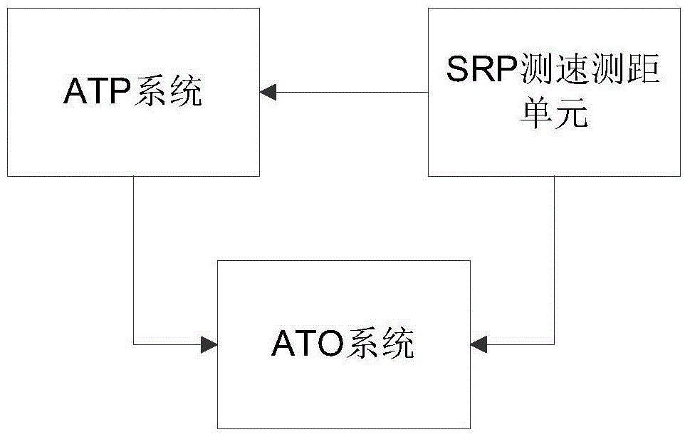
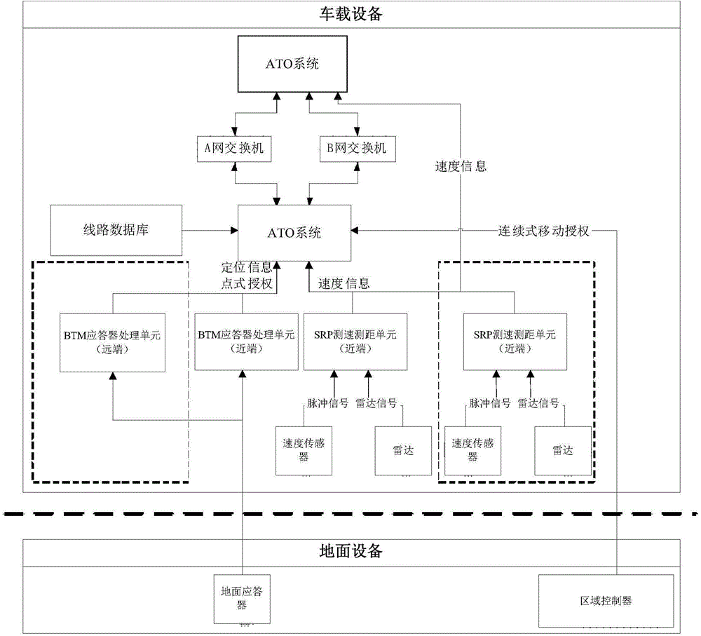
[0035] figure 1 It is a schematic diagram of an ATO speed measurement and distance measurement system provided by an embodiment of the present invention. Such as figure 1 As shown, the system mainly includes:

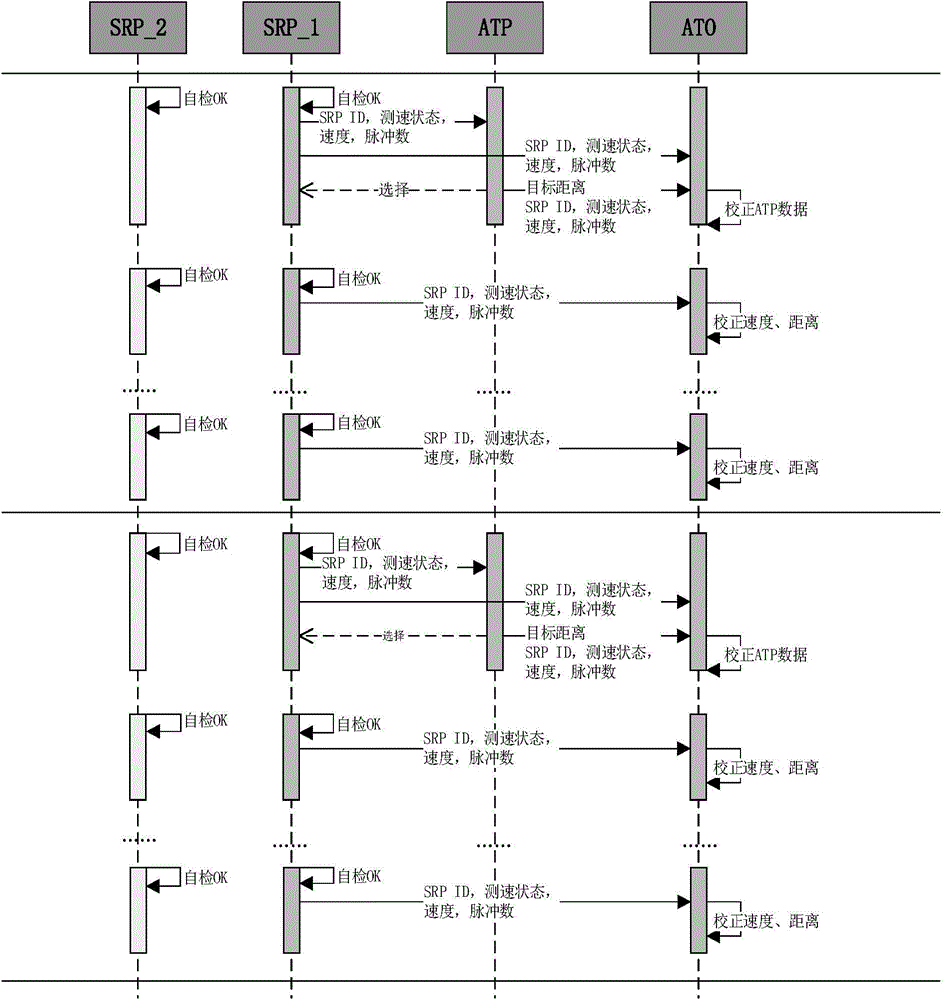
[0036] The ATP system is used to periodically send the target distance calculated according to the information sent by the ground equipment, as well as the identification ID, speed sensor data, radar sensor data and speed measurement status of the SRP speed measurement and distance measurement unit obtained through the SRP speed measurement and distance measurement unit to the ATO system;

[0037] The SRP speed measurement and distance measurement unit is used to obtain speed sensor data and radar sensor data, and obtain the speed measurement status according to the obtained speed sensor data and radar sensor data; periodically send the above information and the ID of the SRP speed measurement and distance measurement unit To the ATO system and the ATP system; wherei...


PUM


Abstract

The invention discloses an ATO (automatic train operation) velocity-measuring ranging system. In the system, an ATO system velocity-measuring ranging function is realized by calculating on the basis of ATP data and SRP velocity-measuring ranging unit data. The ATO system is only communicated with an ATP (automatic train protection) unit and an SRP velocity-measuring ranging unit, and connection with a speed sensor, a radar and a BTM processing unit is not needed. Under the condition of meeting the train control precision demand, the purpose of simple and clear structure is achieved. Besides, on the basis of the ATP velocity-measuring ranging data, the information of the SRP velocity-measuring ranging unit is combined by the ATO system, and the velocity-measuring ranging data is corrected, so that the accuracy of the velocity-measuring ranging data meets the train control requirement.

Description

technical field [0001] The invention relates to the technical field of rail transit, in particular to an ATO speed measurement and distance measurement system. Background technique [0002] With the rapid development of urban rail transit and information technology, communication-based train control system (referred to as CBTC) has been widely used in urban rail transit signaling systems. The extensive application of the CBTC system has effectively shortened the tracking interval of trains and improved the operating efficiency of rail transit. As an important part of the CBTC system, the automatic train driving subsystem (ATO for short) can reduce the labor intensity of the driver, improve the comfort of train operation, and reduce the energy consumption of train operation. In the current rail transit construction, the train automatic driving subsystem has been generally configured, and most of the new lines have realized the direct opening of the automatic driving function...

Claims


Application Information

Patent Timeline
Patent Type & Authority Applications(China)
IPC IPC(8): B61L25/02
Inventor 孟军陈宁宁李亮尹逊政徐意王芃许硕王超孙旺孙磊贾鹏郑伟徐伟宾海丰王俊锋黄苏苏
Owner 广州铁科智控有限公司
Learn More